Sealing fastener

a technology of fasteners and seals, which is applied in the direction of fastening means, screws, pins, etc., can solve the problems of affecting the installation of seals

Inactive Publication Date: 2006-05-11
ILLINOIS TOOL WORKS INC
View PDF21 Cites 51 Cited by
  • Summary
  • Abstract
  • Description
  • Claims
  • Application Information

AI Technical Summary

Problems solved by technology

Installing the seal as a separate part is cumbersome and awkward, complicating installation of the fastener.
If installed on the fastener in advance, the seal can become dislodged, even if properly placed on the fastener.
In automated assembly plants, a fastener missing a seal may not be detected and may be installed on the article in which it is used inadvertently.
A loose fastener of this type will rattle or squeak, may provide a path for the penetration of moisture and may not adequately secure the second article or item as required.
If the seal is adhered to the skirt of the fastener, the seal may not function optimally if the fastener is not seated squarely in the panel.
Further, the position of the seal relative to the fast

Method used


Image

  • Sealing fastener
  • Sealing fastener

Examples


Embodiment Construction

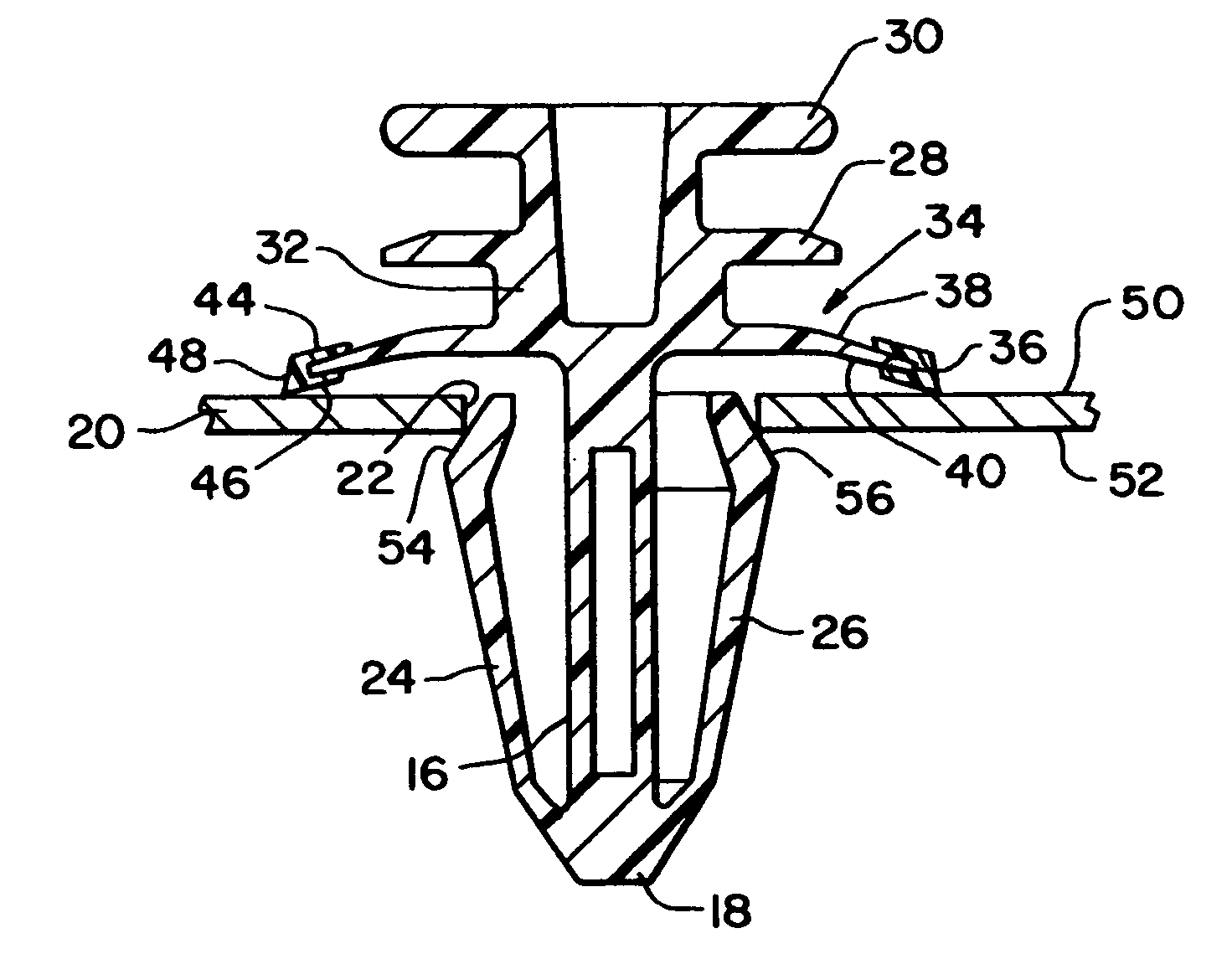
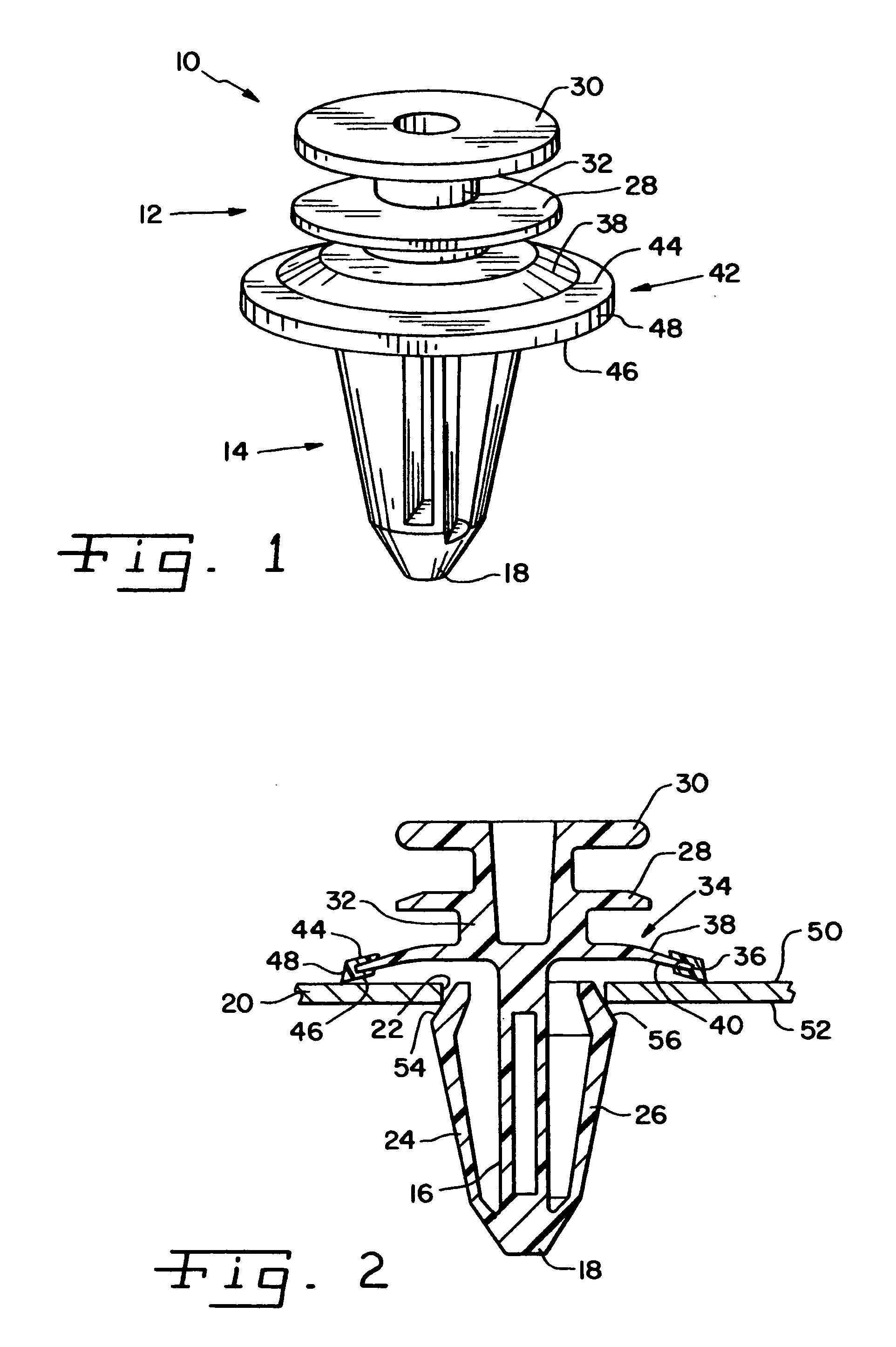
[0016] Referring now more specifically to the drawings and to FIG. 1 in particular, numeral 10 designates a fastener in accordance with the present invention. The fastener 10 includes a head 12 and a snap engaging stem 14. Head 12 and stem 14 can be formed as a monolithic body by injection molding or other suitable molding or fabrication process. The material for fastener 10 can be selected as optimally desirable for its particular installation and use. Accordingly, fastener 10 can be formed of plastic, such as nylon. It should be understood that the exemplary embodiment for fastener 10 and the particular configurations for snap engaging stem 14 and head 12 are provided as suitable for the particular installation.

[0017] Snap engaging stem 14 includes a post 16 having a distal end 18. Post 16 is connected to head 12 at an end of post 16 opposite distal end 18. An engagement means is associated with snap engaging stem 14 for securing fastener 10 relative to an object such as a panel ...


PUM


Abstract

A sealing fastener includes a sealing flange for engaging a surface of an article in which the fastener is installed. The sealing flange has a concave skirt with a seal attached to a peripheral edge of the skirt.

Description

CROSS-REFERENCE TO RELATED APPLICATIONS [0001] The present regular U.S. patent application claims the benefits of U.S. Provisional Application Ser. No. 60 / 625,293 filed on Nov. 5, 2004.FIELD OF THE INVENTION [0002] The present invention relates generally to fasteners and, more particularly, the invention pertains to push-in type fasteners having seals for creating a barrier to the penetration of moisture, dust and noise through an aperture in which the fastener is secured. BACKGROUND OF THE INVENTION [0003] Push-in type fasteners are used in a variety of assemblies to secure components of the assembly. For example, in automobiles stud-like fasteners are used to secure trim parts to body panels. The fastener includes a stem with deflectable members for securing the fastener to a body panel through an aperture in the panel through which the stem is pushed. A head attached to the stem is configured for attachment to the trim part. The deflectable members are pushed through the panel an...

Claims


Application Information

Patent Timeline
IPC IPC(8): F16B33/00
CPCF16B19/008F16B21/086
Inventor MOERKE, BENJAMIN H.
Owner ILLINOIS TOOL WORKS INC
Why Eureka
Try Eureka