Method and apparatus for storing vacuum gauge calibration parameters and measurement data on a vacuum gauge structure

a technology of vacuum gauge and calibration parameters, which is applied in the direction of vacuum gauges using ionisation effects, instruments, measurement devices, etc., can solve the problems of gauges either malfunctioning or failing, manufacturers have difficulty in determining the cause of malfunction or failure, and inaccuracy in vacuum measurements also aris

Active Publication Date: 2006-06-15
MKS INSTR INC
View PDF21 Cites 26 Cited by
  • Summary
  • Abstract
  • Description
  • Claims
  • Application Information

AI Technical Summary

Benefits of technology

The patent text discusses the issue of inaccuracies in vacuum measurements caused by the interaction between sensors in combination vacuum gauges. This is particularly problematic when using an ionization gauge and a heat-loss sensor, as the heat generated by the ionization gauge can affect the heat-loss sensor. The text highlights that the combination vacuum gauge is hottest near the ionization gauge filament, resulting in temperature gradients that affect the heat-loss sensor temperature compensating equations. The technical effect of this patent is to provide a solution for accurately measuring vacuum in combination vacuum gauges, even when there is an interaction between sensors.

Problems solved by technology

The technical problem addressed in this patent text is the need for accurate vacuum measurements using combination vacuum gauges, which require different correction factors for each sensor due to variations in pressure, operation parameters, temperature, gas species, and sensor type. The current practice of calibrating sensors with generic correction factors leads to inaccurate measurements, especially when the measurements from two sensors overlap in a given pressure range and their measurement signals combine into a blended output signal. The solution proposed is to provide unique correction factors for each individual sensor of the combination vacuum gauge through a memory module that can be plugged into the controller electronics, allowing for field replacement of the gauge with the memory module.

Method used


Image

  • Method and apparatus for storing vacuum gauge calibration parameters and measurement data on a vacuum gauge structure
  • Method and apparatus for storing vacuum gauge calibration parameters and measurement data on a vacuum gauge structure
  • Method and apparatus for storing vacuum gauge calibration parameters and measurement data on a vacuum gauge structure

Examples


Embodiment Construction

[0016] A description of preferred embodiments of the invention follows.

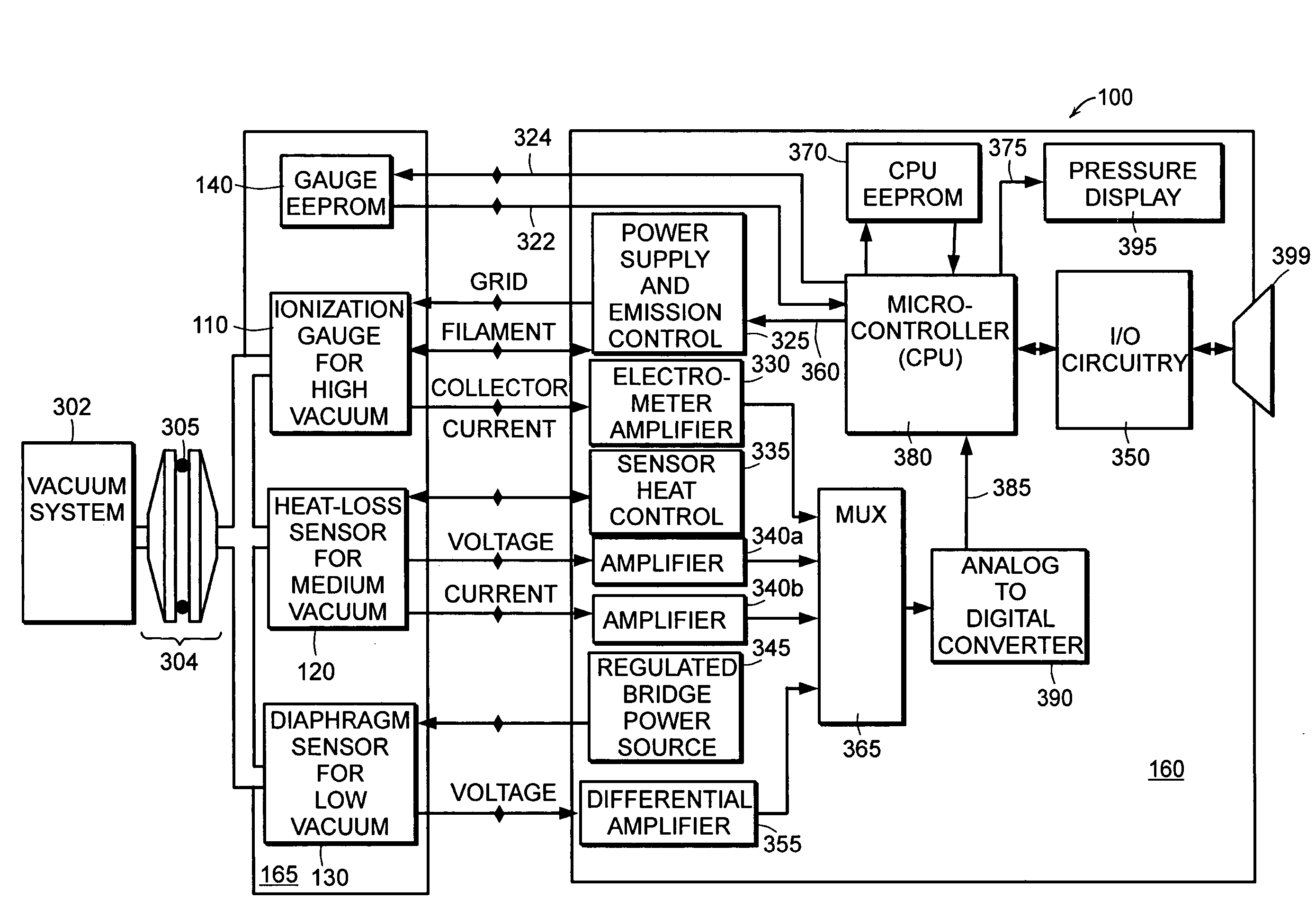
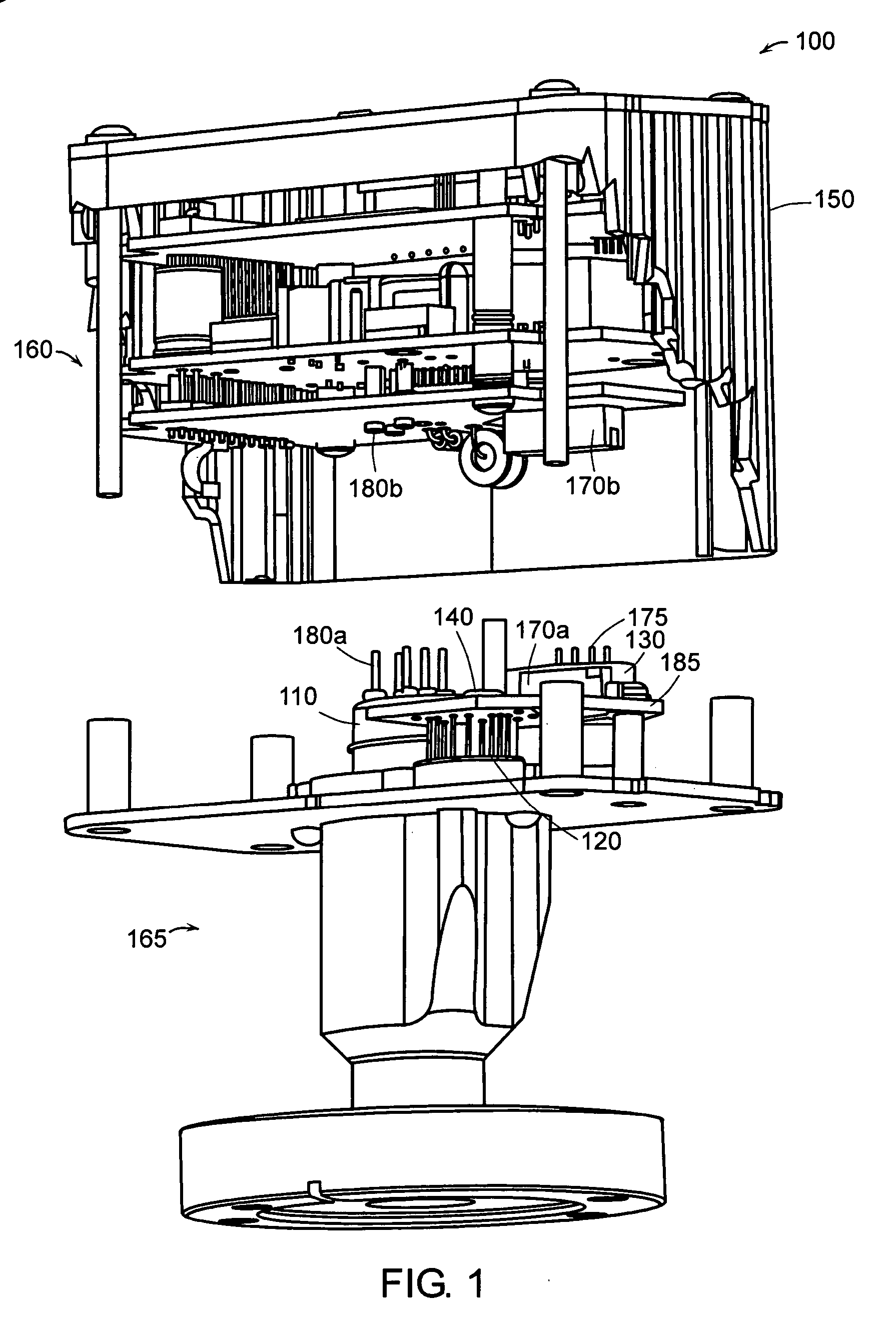
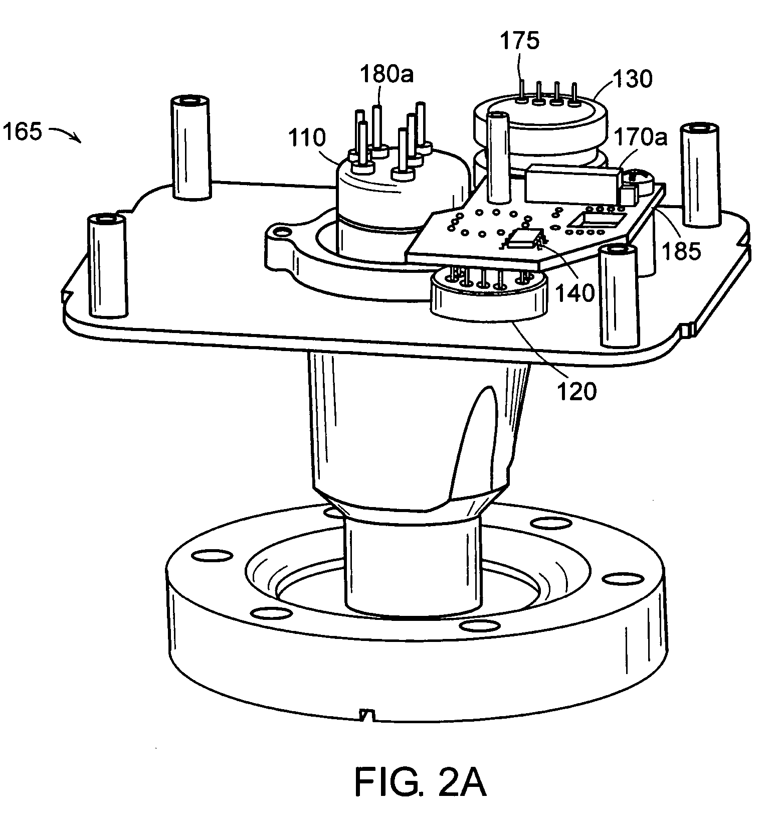
[0017] Referring to FIG. 1, a combination vacuum gauge system 100 in accordance with the present invention comprises a combination vacuum gauge 165 and controller electronics 160. The combination vacuum gauge 165 comprises an ionization gauge 110, a heat-loss sensor 120, a diaphragm sensor 130, and nonvolatile memory 140. The ionization gauge 110 electrically connects to the controller electronics 160 through pins 180a and sockets 180b. The heat-loss sensor 120 and the nonvolatile memory 140 are connected to a combination vacuum gauge circuit board 185 which connects to the controller electronics 160 through connectors 170a and 170b. The diaphragm sensor 130 electrically connects to the controller electronics 160 through pins 175 and a flex cable (not shown) to the connectors 170a and 170b. The controller electronics 160, when connected to the combination vacuum gauge 165, are enclosed within a housing 150.

[001...


PUM


Abstract

A method and apparatus for measuring gas pressure by combining an ionization gauge with at least one other vacuum sensor. Nonvolatile memory coupled to the vacuum gauge contains calibration parameters unique to each individual sensor based on factory calibration. The nonvolatile memory may contain calibration parameters for a heat-sensitive vacuum sensor to compensate for the temperature gradients generated by the ionization gauge. The calibration parameters are a function of calibration data determined when the ionization gauge is both on and off. The nonvolatile memory may store a window of measurement data of the vacuum gauge that is updated at predetermined time intervals and in response to an event, such as an error event, to aid in investigating the cause of vacuum gauge malfunction or failure.

Description


Claims


Application Information

Patent Timeline
Owner MKS INSTR INC
Why Eureka
Try Eureka