Time interval indicating device

a technology of time interval and indicating device, which is applied in the direction of electromechanical unknown time interval measurement, instruments, etc., can solve the problems of not being well suited to providing an indication of the time remaining in an activity, not being well suited for use, and not being able to provide a clear indication of an individual's progress in an activity

Active Publication Date: 2006-06-22
LEARNING RESOURCES
View PDF20 Cites 34 Cited by
  • Summary
  • Abstract
  • Description
  • Claims
  • Application Information

AI Technical Summary

Benefits of technology

[0005] A device for indicating the passage of two or more time intervals is provided. In the illustrated embodiment, the device includes a base portion with a user interface and a light portion. The light portion includes two or more lights, which may be of different colors, disposed in a vertical arrangement above the base portion. The user interface includes a display and a keypad for programming the device with on

Problems solved by technology

Although the foregoing count-up devices are often useful for telling the time of day and for timing simple events such as a race by use of a simple “lap” time functionality, such devices are not well suited for providing an indication of the time remaining in an activity.
However, such count-down devices do not typically provide a clear indication of an individual's progress in an activity since the devices often require an event participant to calculate, interpret or judge how much time is remaining in the active interval and estimate or extrapolate his or her progress relative to the total length of the activity.
Moreover, such devices place a particular importance on the instant of time expiration by providing a single audible or visual signal, and they are not well-suited for use with activities having multiple steps or intervals or providing a gentle and/or progressive warning for assisting a participant

Method used


Image

  • Time interval indicating device
  • Time interval indicating device
  • Time interval indicating device

Examples


Embodiment Construction

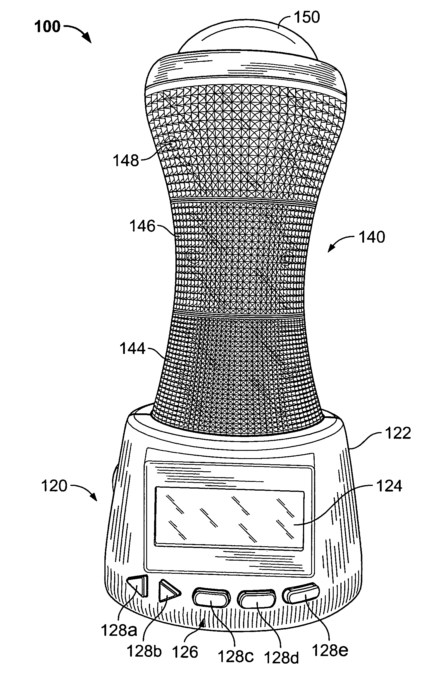
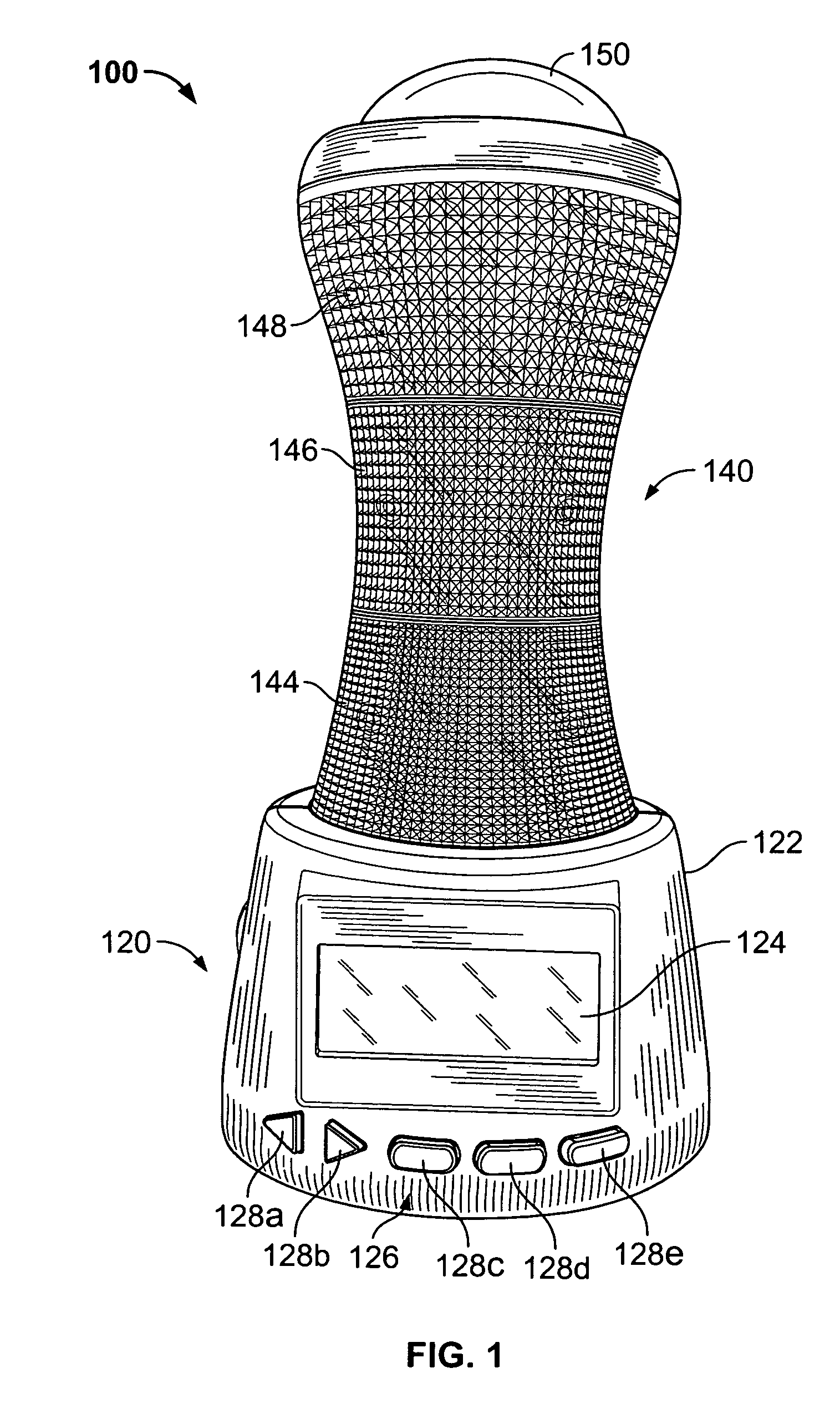
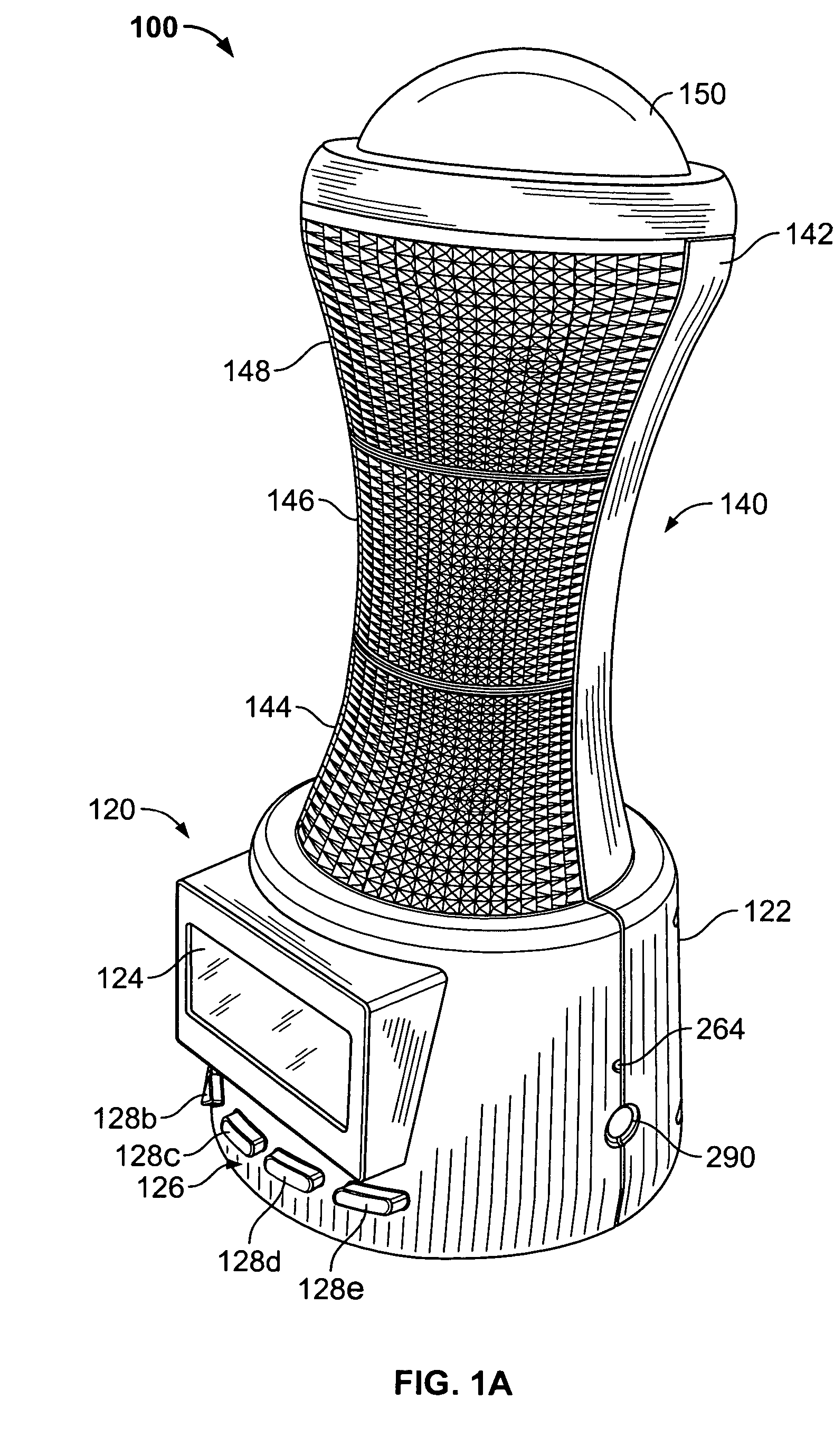
[0012] Referring now to the figures, particularly FIGS. 1, 1A and 1B, an exemplary time interval indicating device is shown. As shown in FIG. 1, the exemplary time interval indicating device 100 has a generally hourglass-shaped housing including a base portion 120 and an upper, lighted portion 140. As shown, the base portion 120 has a generally truncated cone shape and the base portion housing 122 is molded or otherwise formed from a plastic material in two distinct halves (i.e., front and back), which are secured together by fasteners such as screws or the like. As shown in FIGS. 1A and 1B, the rear portion of the base housing 122 extends upward to form the back housing half 142 of the upper portion 140. As shown in FIGS. 1, 1A and 1B, the front half of the upper portion 140 is formed of a transparent or translucent material such as plastic or glass to permit light transmission therethrough. As shown, the front half of the upper portion 140 is segmented in three lighted sections 14...


PUM


Abstract

A device for indicating the passage of two or more time intervals is provided. In one embodiment, the device includes a base portion with a user interface and a light portion. The light portion includes three lights of different colors that are disposed in a vertical arrangement above the base portion. The user interface includes a display and a keypad for programming the device with one or more time durations, and for associating one or more of the lights with each time interval. A controller is in communication with the user interface and operatively coupled with the lights to illuminate and turn off each light during its associated interval. The device may include an audio section linked to the controller for further indicating the intervals or transitions therebetween by outputting one or more sounds.

Description

FIELD OF THE INVENTION [0001] This invention generally pertains to timing devices, and more particularly to a device for indicating the passage of time intervals. BACKGROUND OF THE INVENTION [0002] Various devices are known in the art for timing events. Timers may be categorized in one of two groups as either an incremental (i.e., count-up) or decremental (i.e., count-down) device. Various mechanical, electromechanical, and electrical clocks or stopwatches have been employed to tell time and / or time activities and events in a count-up manner. Such count-up devices typically provide a visual indication using hands or numerals for designating the hour, minute and second of the time of day or elapsed time of the activity. Although the foregoing count-up devices are often useful for telling the time of day and for timing simple events such as a race by use of a simple “lap” time functionality, such devices are not well suited for providing an indication of the time remaining in an activ...

Claims


Application Information

Patent Timeline
IPC IPC(8): G04B19/00
CPCG04G11/00G04G15/006G04C17/02G04C19/02G04F1/00
Inventor GORDON, GAYLE E.VICTOR, NG KWOK-HO
Owner LEARNING RESOURCES
Why Eureka
Try Eureka