
Gas pressure regulator

Inactive Publication Date: 2006-06-29
EIP MANAGEMENT
View PDF8 Cites 27 Cited by
  • Summary
  • Abstract
  • Description
  • Claims
  • Application Information

AI Technical Summary

Problems solved by technology

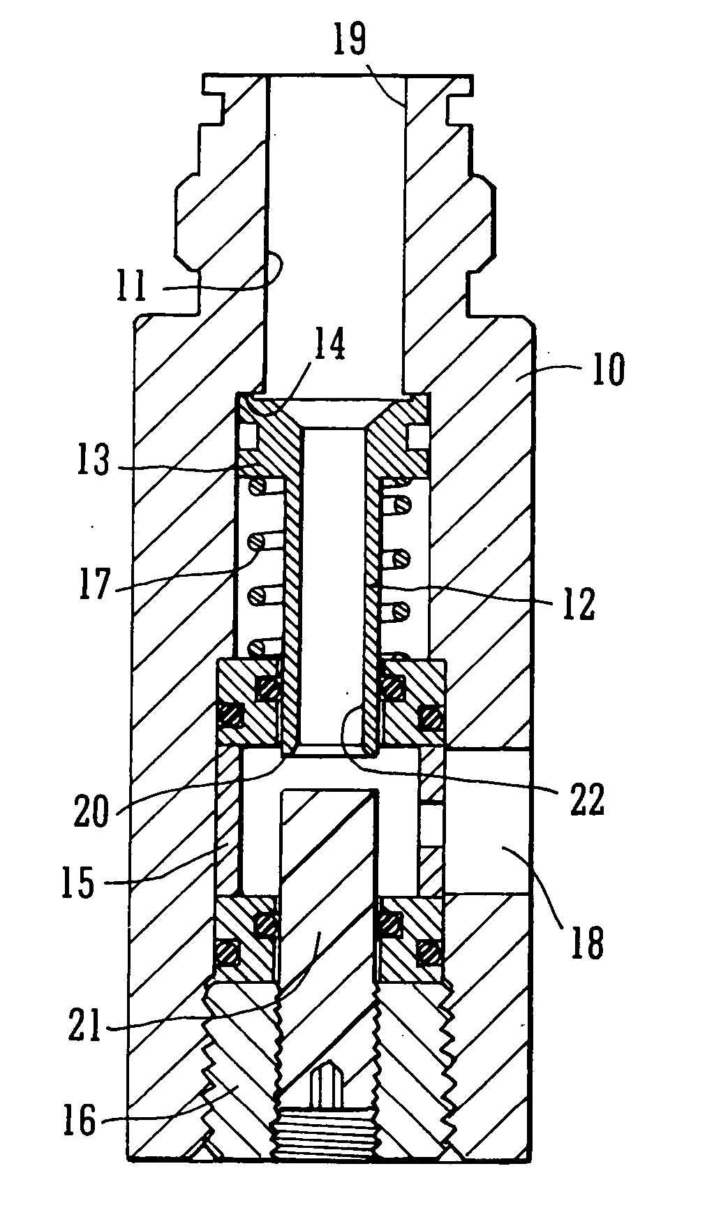
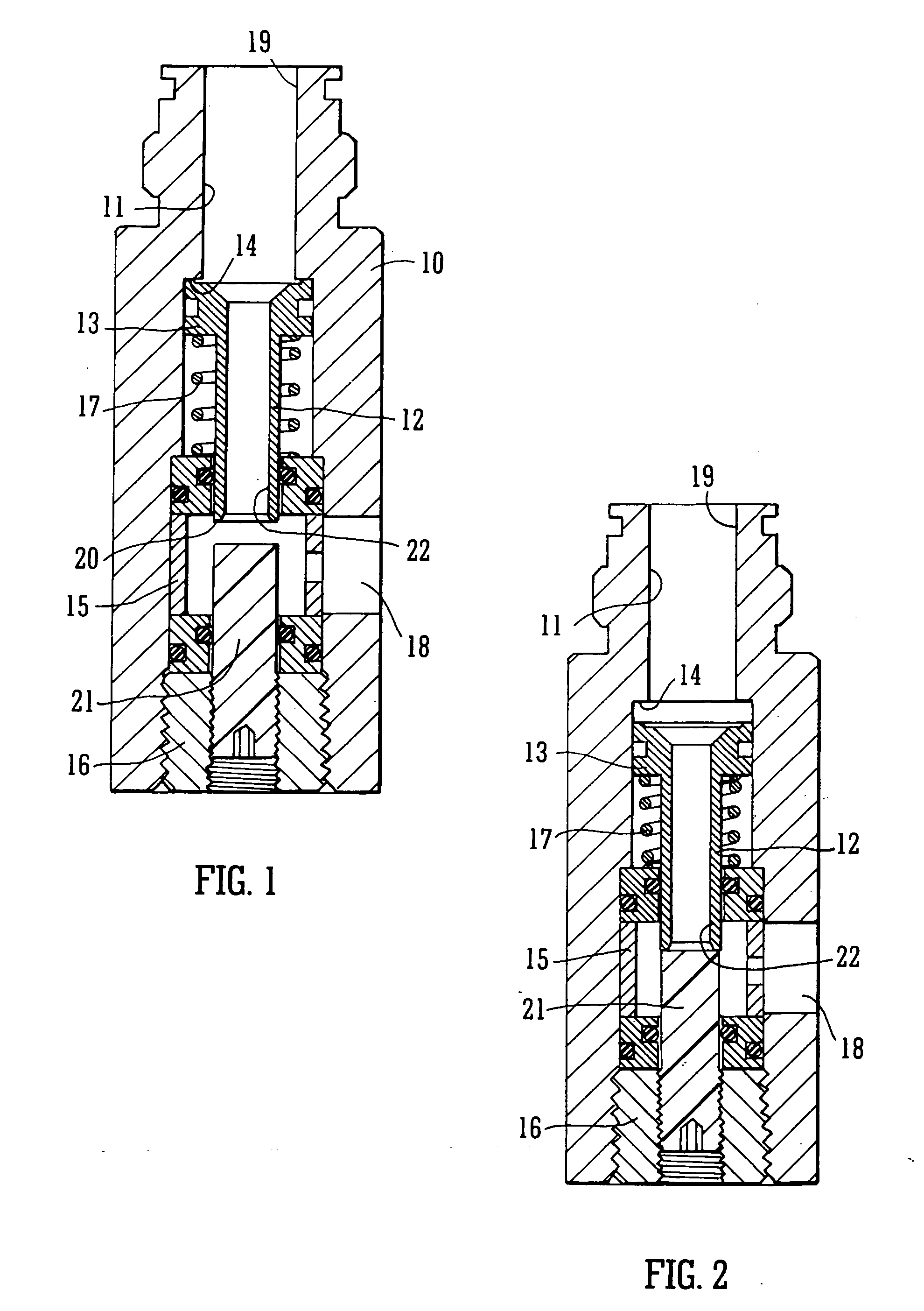
A disadvantage of this prior art regulator is that the valve member 12 is under the influence of gas pressure acting on its end surface 20 counter to pressure acting on its enlarged end 13 and tending to keep the valve member in the valve-open position.

Method used


Image

  • Gas pressure regulator
  • Gas pressure regulator
  • Gas pressure regulator

Examples


Embodiment Construction

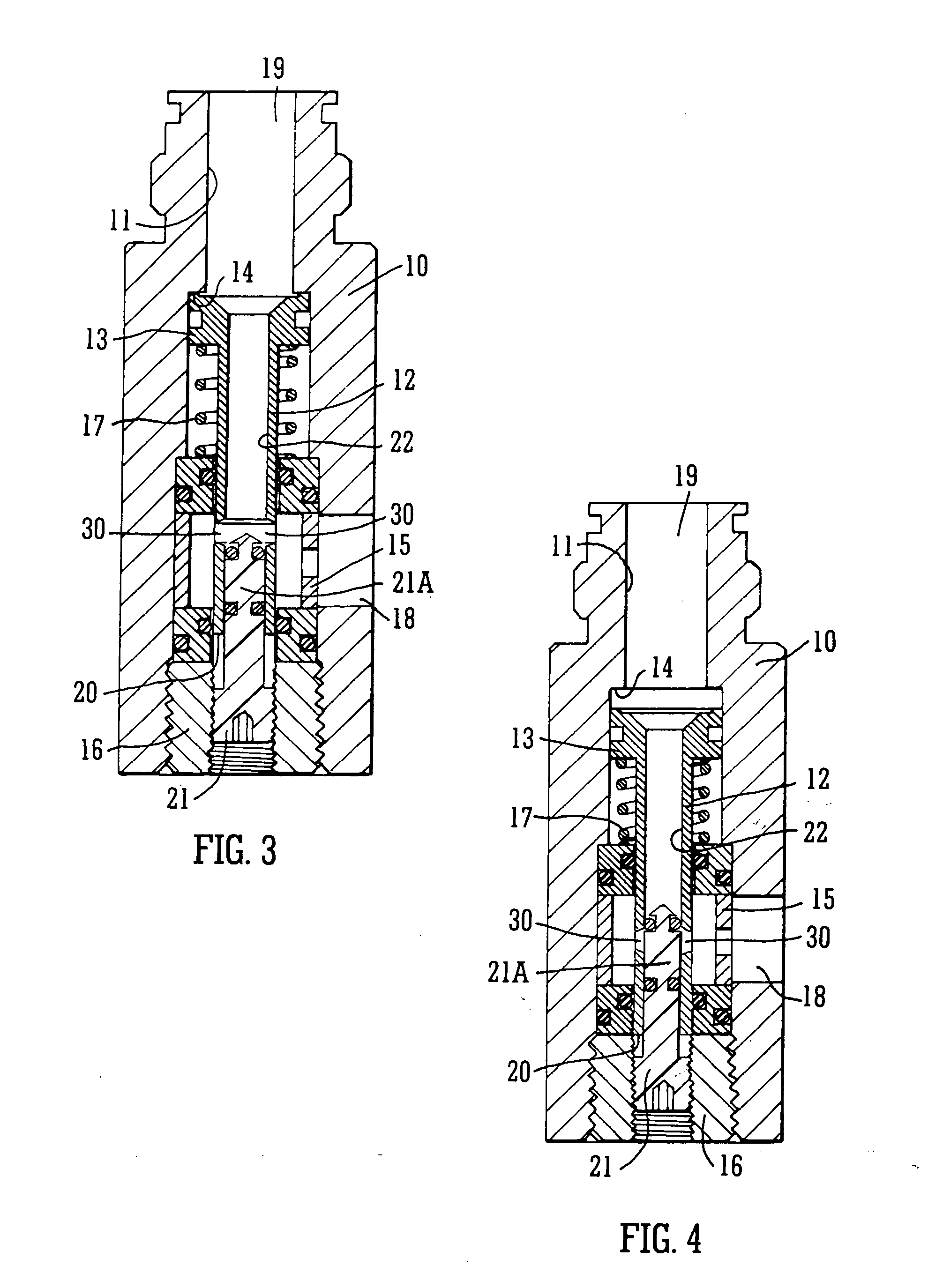
[0022] So far as the regulators of FIGS. 3 and 4 and of FIGS. 5 and 5A resemble the regulator of FIGS. 1 and 2 like parts have been given like references. Each comprises a housing 10 having a through bore 11 in which a tubular valve member 12 is moveabIle between valve-open and valve-closed positions. The housing 10 has a lateral inlet 18 and the upper end 19 of the bore of the housing constitutes an outlet. A spring 17 is in compression between the underside of an enlargement 13 at the upper end of the valve member 12 and an adjustment cylinder 15 which surrounds the valve member within the bore 11, the cylinder being axially moveable by a nut 16 engaging screw threads at the lower end of the bore 11.

[0023] In the embodiment of FIGS. 3 and 4 the lower end 20 of the valve member 12 does not terminate above the plug 21. Instead a lower end portion of the valve member 12 receives an upper portion 21 A of the plug as a gas-tight, sliding fit after the fashion of a piston. The wall of ...


PUM


Abstract

A gas pressure regulator of the kind in which a valve member is spring biased to the valve-open position and is moved to the valve-closed position when upstream pressure at an outlet overcomes the spring is arranged such that gas pressure at an inlet end of the valve member 12 does not influence it in the valve-opening direction. In the embodiment of FIGS. 3 and 4 a bottom end of the valve member receives a piston-like plug. Openings in the wall of the valve member are occluded when the valve is closed. In the open position of the valve-member pressure is equal all round each opening. In another embodiment of the invention a spool is provided having one enlarged end within the valve member and another outside it. Pressure on the combined surfaces of the end and the end of the valve member is equal to the pressure on the end of the spool.

Description

[0001] This Application claims priority from British Patent Application No. 0428167.1 filed Dec. 23rd, 2004. FIELD OF THE INVENTION [0002] This invention relates to an improved gas pressure regulator. BACKGROUND OF THE INVENTION [0003] Nearly all systems using a gas supply need the utility to which the gas is being supplied to have a regulator. The function of the regulator is to prevent wide variations in the pressure being supplied and in particular to shut off the supply if the pressure is too high. A regulator is especially needed when the source of the gas is a container in which gas is stored at high pressure to ensure that excessive pressure will not be experienced within a utility connected to the container. [0004]FIGS. 1 and 2 of the accompanying drawings illustrate a known regulator respectively in the valve-open and the valve-closed position. A housing 10 has a through bore 11 in which a tubular valve member 12 is moveable. The valve member has an enlarged upper end 13 wh...

Claims


Application Information

Patent Timeline
Patent Type & Authority Applications(United States)
IPC IPC(8): G05D16/10F16K17/04F16K17/30
CPCF16K17/046F16K17/30Y10T137/7808Y10T137/7834F16K17/06G05D16/10
Inventor CARNALL, MARTIN
Owner EIP MANAGEMENT
Learn More