Method for fitting an orthopedic brace to the body

a technology for orthopedic braces and body, applied in the field of orthopaedic braces, can solve the problems of time-consuming and laborious remounting on the body, reducing the probability of user achieving a repeatable close fit with each readjustment, and reducing the accuracy of the fi

Active Publication Date: 2006-07-13
BREG
View PDF47 Cites 24 Cited by
  • Summary
  • Abstract
  • Description
  • Claims
  • Application Information

AI Technical Summary

Benefits of technology

[0017] A body section is positioned between the first and second longitudinal brace assemblies. Each of the first, second, third and fourth strap attachment members is coupled with each of the first, second, third and fourth strap connection members, respectively, so that the second side segments connect the first and second longitudinal brace assemblies to one another about the body section. The second side segments is displaced to slide each of the first, second, third and fourth straps through each of the first, second, third and fourth strap guide members, respectively, to render the first side segments more taut. Each of the strap locks is transitioned from the open position to a closed position, thereby changing each of the first side segments from the arbitrary length to a desired fixed length. The second end segments are displaced to slide each of the first, second, third and fourth straps through each of the first, second, third and fourth strap attachment members, respectively, to render the second side segments more taut and change the second side segments from the arbitrary length to a desired fixed length.

Problems solved by technology

Readjustment of the fit of an orthopedic brace to the body every time the orthopedic brace is removed and subsequently remounted on the body can be time-consuming and tedious.
In addition, the probability of the user achieving a repeatable close fit with each readjustment diminishes with each removal and remounting sequence.

Method used


Image

  • Method for fitting an orthopedic brace to the body
  • Method for fitting an orthopedic brace to the body
  • Method for fitting an orthopedic brace to the body

Examples


Embodiment Construction

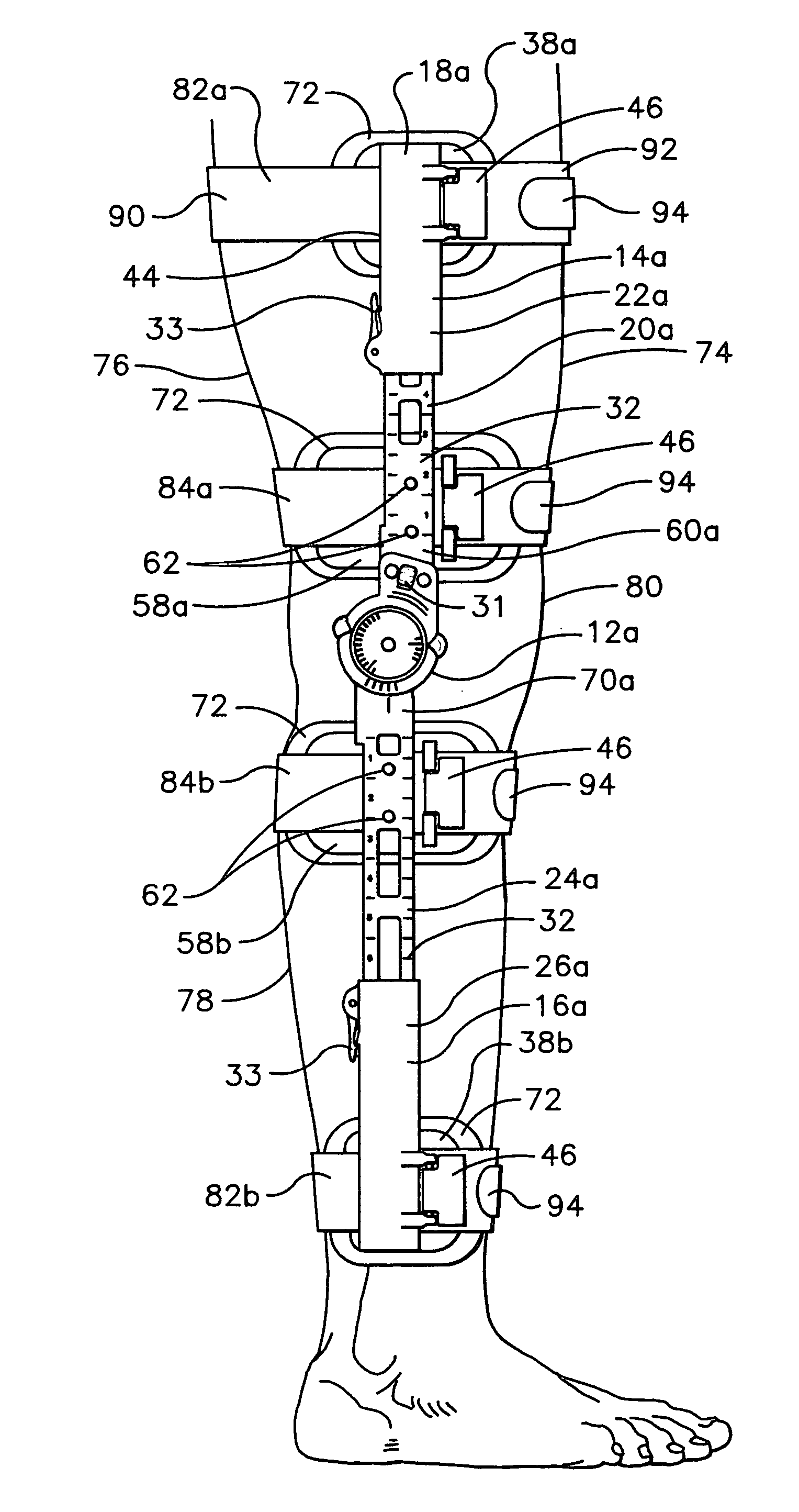
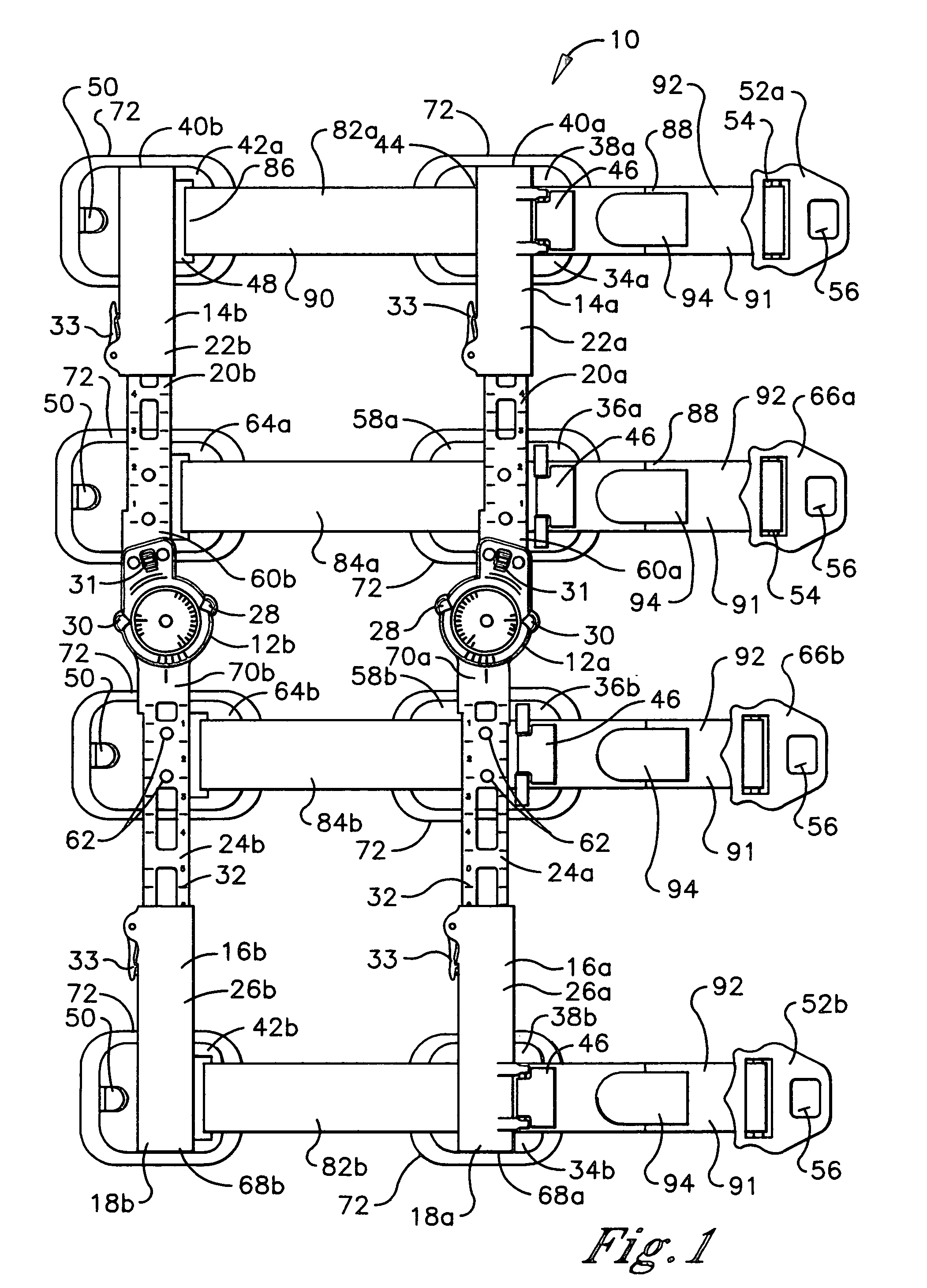
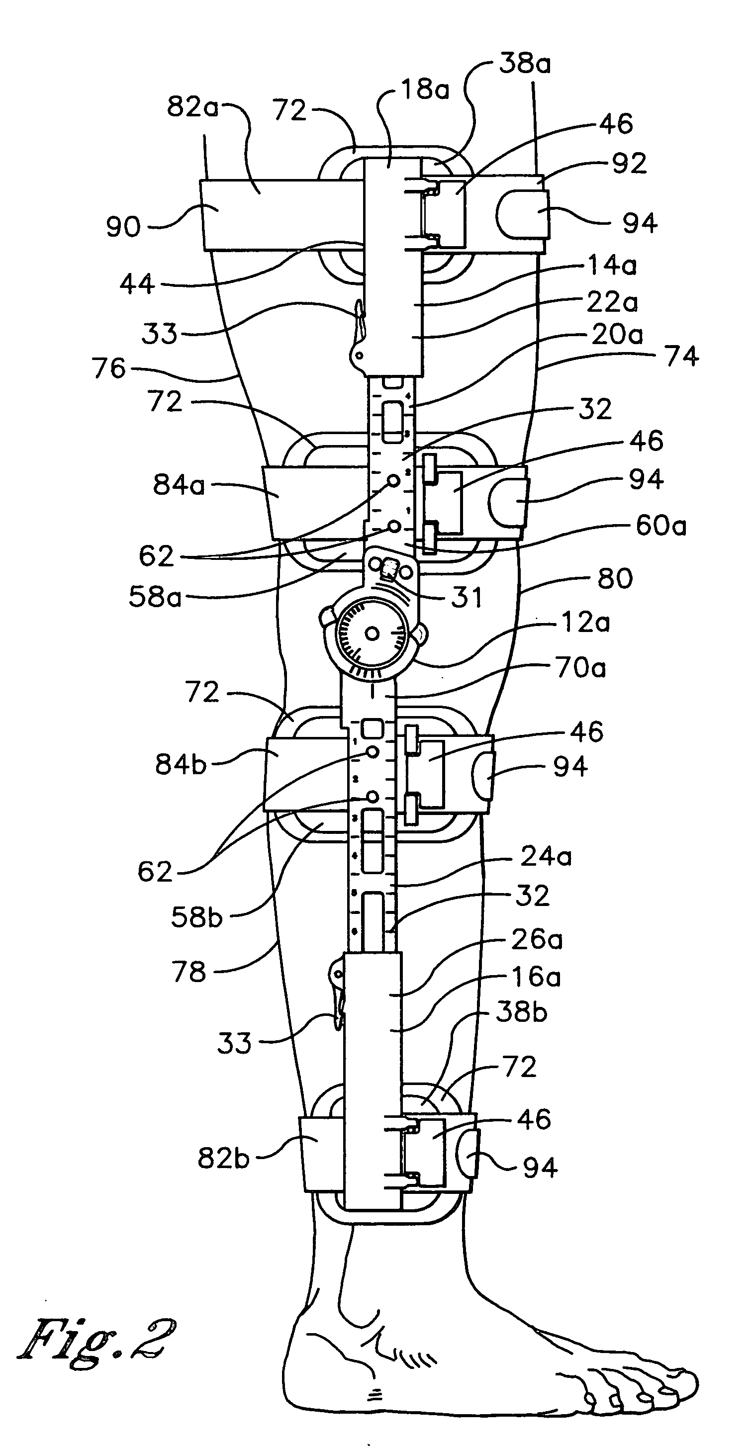
[0035] Referring initially to FIG. 1, an orthopedic brace is shown and generally designated 10, which has utility in a method of the present invention. There are a number of relative terms defined below which are used in the following description to distinguish various elements of the orthopedic brace 10 from one another, but which are not to be construed as limiting the scope of the invention. The relative terms “medial” and “lateral” characterize certain elements of the orthopedic brace 10 and, in particular, describe the relative proximity of the given element to the central longitudinal axis of the body of the user when the brace 10 is mounted thereon. A “medial” element is closer to the central longitudinal axis of the body, while a “lateral” element is further from the central longitudinal axis of the body.

[0036] The terms “proximal” and “distal” characterize certain elements of the brace 10, which are aligned with the longitudinal axis of the brace 10. The terms describe the...


PUM


Abstract

A method is provided for securely fitting an orthopedic brace to the body by means of a plurality of straps, strap locks, strap attachment members, and strap connection members. The method retains the close fit of the brace to the body without the need for substantial readjustment of the fit even after repeated removal and remounting of the brace on the body. The method also enables repositioning the brace on the body without requiring removal of the brace from the body or substantial readjustment of the fit.

Description

[0001] This a continuation of Ser. No. 11 / 039,056, filed on Jan. 12, 2005, which is incorporated herein by reference.TECHNICAL FIELD [0002] The present invention relates generally to orthopedic braces, and more particularly to a method for securely fitting an orthopedic brace to the body. BACKGROUND OF THE INVENTION [0003] Orthopedic braces are worn on the body of a user either to support a healthy skeletal joint that is at risk of injury or to stabilize a skeletal joint that has been destabilized by an injury or other condition. Orthopedic braces generally include rigid structural components to support or stabilize the skeletal joint. Frequently, although not necessarily, the rigid structural components are dynamically linked together by one or more hinges enabling controlled pivotal movement of the skeletal joint during user activity or rehabilitative therapy. The orthopedic brace is mounted on the body such that the hinges traverse the skeletal joint, while the rigid components a...

Claims


Application Information

Patent Timeline
Patent Type & Authority Applications(United States)
IPC IPC(8): A61F5/00
CPCA61F5/0125A61F2005/0139A61F2005/0158A61F2005/0167
Inventor CERIANI, DYLANN D.
Owner BREG
Why Eureka
Try Eureka