Racheting take-up device

a technology of take-up device and racheting, which is applied in the direction of fastening means, mechanical devices, washing machines, etc., can solve problems such as structural interference between itself, and achieve the effect of limiting the amount of expansion experienced

Active Publication Date: 2006-07-20
COMMINS ALFRED D
View PDF27 Cites 41 Cited by
  • Summary
  • Abstract
  • Description
  • Claims
  • Application Information

AI Technical Summary

Benefits of technology

[0019] In selected embodiments, it may be desirable to maintain a take-up device in a contracted configuration before and during installation. Accordingly, in selected embodiments, a take-up device may include a trigger. A trigger may resist the biasing imposed by the biasing member until installation is complete. Once the trigger is released, a take-up device expands to fill or consume any increase in the distance between the fastener and the structural member. In certain embodiments, a take up device, in accordance with the present invention, may expand up to several inches in length. If desired, an extension stop may be included to limit the amount of expansion experienced by a take-up device. For example, an expansion stop may stop expansion before the biasing member urges separation of the base and slide.

Problems solved by technology

So configured, the locking member may cause a structural interference between itself, the partial receiving volume, and the full receiving volume during translation of the base with respect the slide in a first direction.

Method used


Image

  • Racheting take-up device
  • Racheting take-up device
  • Racheting take-up device

Examples


Embodiment Construction

[0028] It will be readily understood that the components of the present invention, as generally described and illustrated in the drawings herein, could be arranged and designed in a wide variety of different configurations. Thus, the following more detailed description of the embodiments of the system and method of the present invention, as represented in the drawings, is not intended to limit the scope of the invention, as claimed, but is merely representative of various embodiments of the invention. The illustrated embodiments of the invention will be best understood by reference to the drawings, wherein like parts are designated by like numerals throughout.

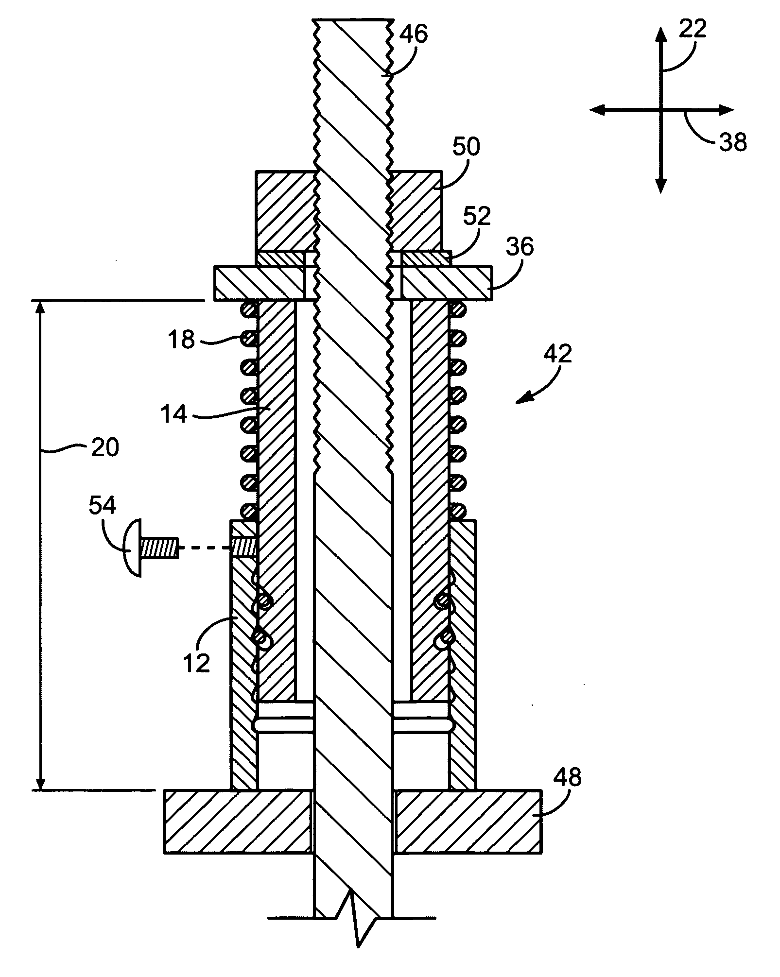
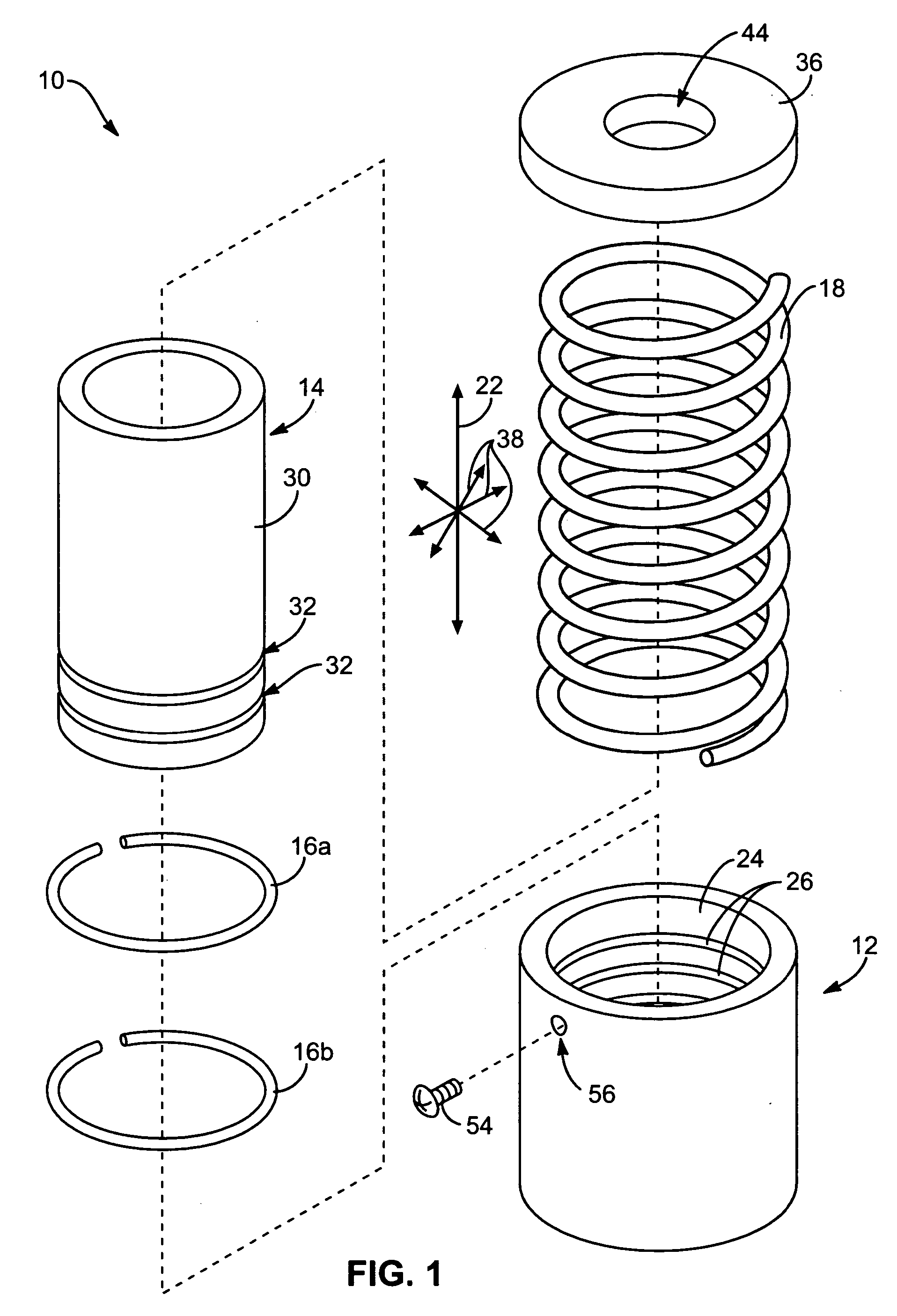
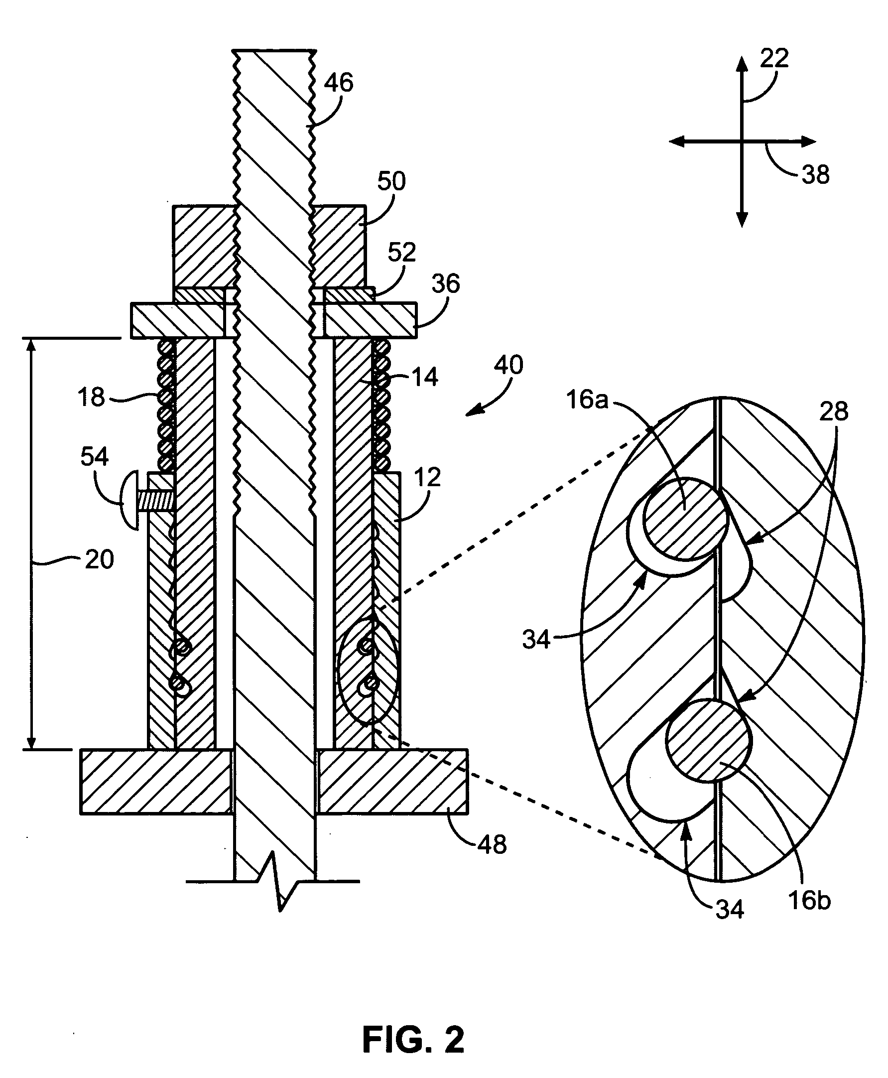
[0029] Referring to FIGS. 1-3, in selected embodiments, a take-up device 10 in accordance with the present invention may include a base 12, a slide 14, one or more locking members 16, and a biasing member 18. In operation, a locking member 16 may be positioned between the base 12 and the slide 14 to control relative motion the...


PUM


Abstract

An apparatus for taking-up slack in a building hold-down system. The apparatus may include a base having a tubular shape, a slide having a tubular shape and a threadless interior surface, a locking member, and a biasing member. The slide may be sized and positioned to translate within the base. The locking member may be positioned between the base and the slide to permit translation of the base with respect to the slide to cause expansion and resist translation of the base with respect to the slide to cause contraction. The biasing member may urge translation of the base with respect to the slide in the direction causing expansion.

Description

RELATED APPLICATIONS [0001] This application claims the benefit of co-pending U.S. Provisional Patent Application Ser. No. 60 / 641,120, filed on Jan. 3, 2005 for RACHETING TAKE-UP WASHER.BACKGROUND [0002] 1. The Field of the Invention [0003] This invention pertains to building construction, and, more particularly, to novel methods and apparatus for anchoring building walls to foundations and lower floors thereof. The invention provides an automatic adjusting mechanism to remove slack in a hold-down system caused by wood shrinkage over time or wood crushing caused by earthquakes. [0004] 2. The Background Art [0005] Strong winds and earthquakes subject walls and others elements of a building to tremendous forces. If these forces are not distributed to the proper elements or structures capable of withstanding such forces, the building may be torn apart. Foundations are often the strongest element of a building. Securely tying the walls of a building to the foundation greatly improves st...

Claims


Application Information

Patent Timeline
Patent Type & Authority Applications(United States)
IPC IPC(8): E04C5/08
CPCE04B1/2604E04B2001/2688F16B5/0266
Inventor COMMINS, ALFRED D.
Owner COMMINS ALFRED D
Why Eureka
Try Eureka