Display device and blower thereof

a technology of display device and blower, which is applied in the direction of electrical apparatus casing/cabinet/drawer, cooling/ventilation/heating modification, instruments, etc., can solve the problems of increasing manufacturing costs, weak heat dissipation efficiency of conventional display device, and increasing dimensions, so as to achieve sufficient heat dissipation and minimize the size (especially the thickness) of the case

Inactive Publication Date: 2006-07-27
LG ELECTRONICS INC
View PDF17 Cites 27 Cited by
  • Summary
  • Abstract
  • Description
  • Claims
  • Application Information

AI Technical Summary

Benefits of technology

[0023] The present invention has been made to solve the above problems, and it is an object of the present invention to provide a display device and a blower thereof, which comprise a single axial flow fan within a case to discharge heat from the interior of the case, thereby minimizing the size (particularly, thickness) of the case while ensuring sufficient heat dissipation only with the single axial flow fan.

Problems solved by technology

However, according to the conventional display device, since it is necessary to arrange the plural axial flow fans 4 within the case 2 so as to obtain uniform heat dissipation of the case 2, the case 2 has a complicated structure, and is increased in its dimensions, thereby increasing manufacturing costs.
In addition, even if the plural axial flow fans 4 are provided to the case 2, a dead zone is inevitably formed within the case 2, where a blowing force of the axial flow fans 4 is not sufficiently applied, so that the conventional display device suffers from weak heat dissipation efficiency.
Moreover, in the conventional display device, flow resistance is increased due to collision between the forced air flow by the axial flow fans 4 and air flow by natural convection, and between the forced air flows by the axial flow fans 4, causing weak heat dissipation efficiency and severe noise.
Furthermore, in the case where the axial flow fans 4 are directly connected with the fan motors, respectively, the case 2 is inevitably thickened, and in the case where the axial flow fans 4 are indirectly connected with the fan motors via the belt-pulley, a connecting structure between the axial flow fans 4 and the fan motors is further complicated along with an increase in manufacturing costs, in spite of relative decrease in thickness of the case 2.

Method used


Image

  • Display device and blower thereof
  • Display device and blower thereof
  • Display device and blower thereof

Examples


first embodiment

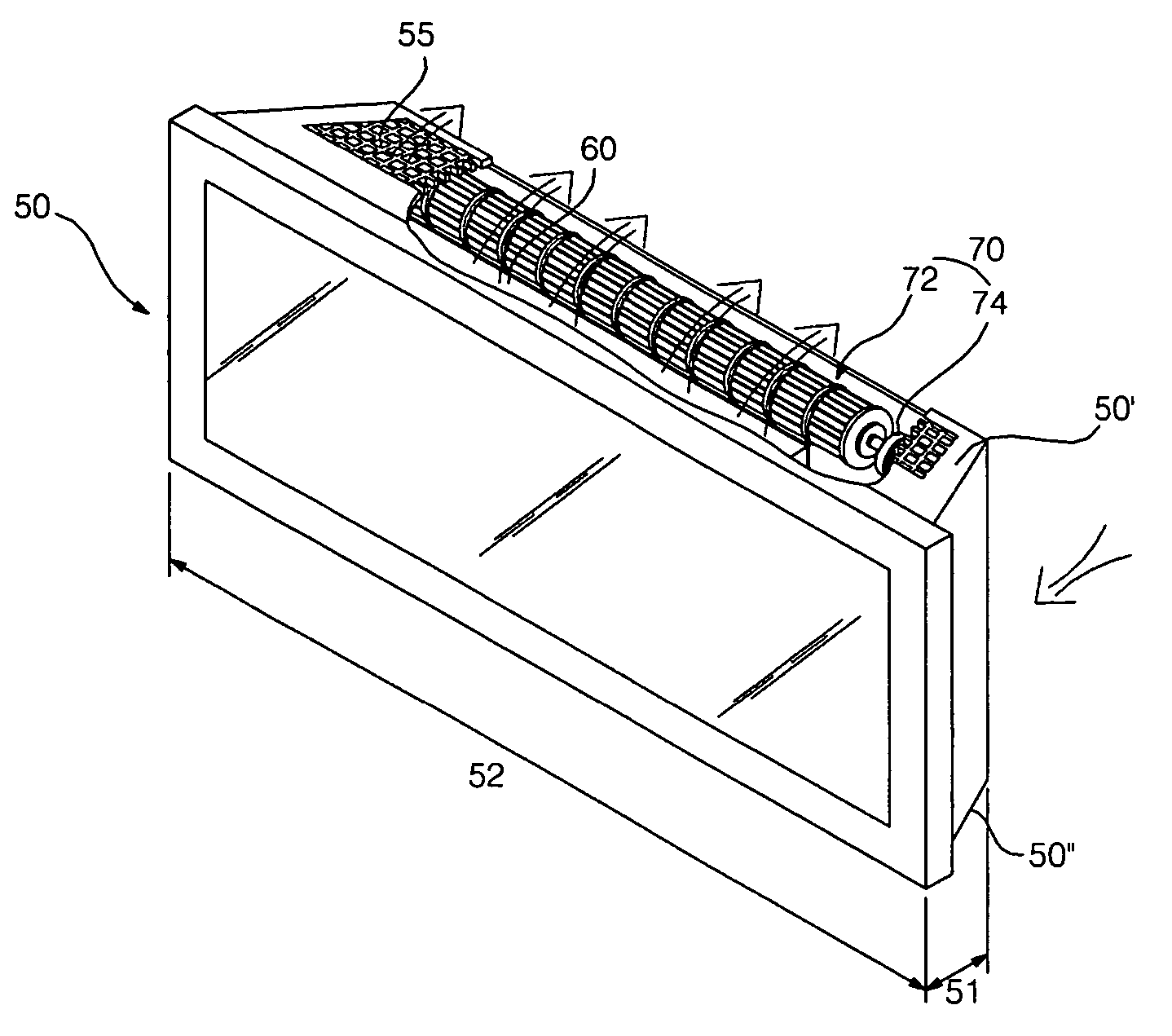
[0091] Heat dissipation of the display device and the blower thereof constructed as described above will be described as follows.

[0092] Air flow is generated by natural convection within the case 50, causing external air to be induced from the outside to the case 50, and internal air in the case 50 to be discharged to the outside of the case 50.

[0093] In particular, when the fan motor 74 is driven to rotate the axial flow fan 72, forced air flow is generated by the axial flow fan 72 within the case 50 so that heat is more efficiently discharged from the interior of the case 50 to the outside.

[0094] In other words, the external air is forcibly induced to the case 50 through the air inlet 54 of the case 50. The internal air in the case 50 is sucked to the axial flow fan 72 while flowing upwardly within the case 50. The air sucked to the axial flow fan 72 is discharged to the air outlet 55 of the case 50 from the axial flow fan 72. The air discharged to the air outlet 55 of the case...

second embodiment

[0098]FIG. 8 is a rear view illustrating a display device and a blower thereof in accordance with the present invention.

[0099] According to the second embodiment, the display device comprises a case 100 which has a display panel encased therein. The case 100 has an air inlet 101 formed at a lower portion of a rear side, an air outlet 102 formed at an upper surface of the case 100, a plurality of axial flow fans 110 and 112 positioned at a lower portion within the case 100, and a fan motor 114 positioned at the lower portion to rotate the axial flow fans 72.

[0100] Although the display device of the second embodiment comprises two or more axial flow fans, the following description will be limited to the case where the display device comprises two axial flow fans 110 and 112.

[0101] The two axial flow fans 110 and 112 are arranged linearly in the left and right direction of the case 100 such that each of the axial flow fans 110 and 112 has a shaft disposed in the left and right direct...

third embodiment

[0106]FIG. 9 is a rear view illustrating a display device and a blower thereof in accordance with the present invention.

[0107] According to the third embodiment, the display device comprises a case 150 which has a display panel encased therein. The case 150 has an air inlet 151 formed at a left side of a rear side, an air outlet 152 formed at a right side of the rear side, an axial flow fan 160 positioned at a right side within the case 150, and a fan motor 162 indirectly connected with the axial flow fan 160 within the case 150 to rotate the axial flow fan 160.

[0108] The fan motor 162 is positioned at the left side of the axial flow fan 162, and is indirectly connected thereto via a pulley belt 163 and the like.

[0109] Since other components of the third embodiment are the same as those of the first embodiment, detailed description thereof will be omitted hereinafter.

[0110] In the display device and the blower thereof according to the third embodiment, forced air flow is widely g...


PUM


Abstract

A display device, and a blower thereof are disclosed. The display device includes an axial flow fan within a case, which has a display panel encased therein. The axial flow fan is provided in a width direction within the case, so that, while being rotated within the case, the axial flow fan generates forced air flow suitable to the case. The forced air flow is generated in a forward direction along with air flow by natural convection within the case.

Description

BACKGROUND OF THE INVENTION [0001] 1. Field of the Invention [0002] The present invention relates to a display device, and a blower thereof. More particularly, the present invention relates to a display device, and a blower thereof, which comprise an axial flow fan equipped within a thin and wide case so as to allow suitable heat dissipation from the case of the display device. [0003] 2. Description of the Related Art [0004] Generally, display devices refer to apparatuses for displaying characters or images, and are generally classified into a cathode ray tube, and a flat panel display having lower weight and volume than the cathode ray tube. [0005] Display panels for the flat panel display include a liquid crystal display panel (LCD), a field emission display panel (FED), a plasma display panel (PDP), and an electro-luminescence (EL) display panel. [0006] The PDP refers to an apparatus to display images through plasma discharge. Since the PDP has a high response rate, and can be ma...

Claims


Application Information

Patent Timeline
Patent Type & Authority Applications(United States)
IPC IPC(8): H05K7/20
CPCG02F1/133382G02F1/133385H05K7/20972H04N5/64
Inventor KIM, WOOKBAE, JUN HOKIM, CHANG JOON
Owner LG ELECTRONICS INC
Why Eureka
Try Eureka