High-frequency electric connector having no ground terminals

a technology of electric connectors and ground terminals, applied in the direction of two-part coupling devices, coupling device connections, printed circuits, etc., can solve the problems of thin signal terminals being prone to deformation or bent, increasing the cost of manufacturing, and increasing the loss of insertion caused by electric connectors in the signal-transmitting circuit, so as to improve the high-speed signal transmission characteristics, increase the electromagnetic coupling, and reduce the loss of signal energy

Inactive Publication Date: 2005-01-18
HONDA TSUSHIN IND
View PDF17 Cites 139 Cited by
  • Summary
  • Abstract
  • Description
  • Claims
  • Application Information

AI Technical Summary

Benefits of technology

With this arrangement a pair of conductors conveying one and the same signal are equal in length so that each signal may travel the same distance to reach the same place at the same time. Thus, the signals traveling the pair set of conductors cause no interference with each other, and no cross talk can be caused. The slots may be staggered in their vertical arrangements. The staggered arrangement of pair sets of conductors has the effect of preventing the cross talk from appearing between adjacent pair sets of conductors.
The pair sets of signal terminals have no grounding conductor therebetween, and therefore, the energy of the signal cannot be lost while passing through the connector. Accordingly the high-speed signal transmission characteristics can be improved.
The slots may be so arranged that a / b may be equal to or smaller than ⅓, where “a” stands for the distance between two signal terminals of each pair set, and “b” stands for the distance between adjacent pair sets. This arrangement has the effect of significantly improving the high-speed signal transmission characteristics while minimizing the size of the electric connector with the density of signal terminals per unit area remaining high.
Counter terminals to be mated with each pair of signal terminals are paired, also. Each pair set of counter terminals is arranged in parallel at the minimum possible interval, and is combined by an intervening insulating member as a whole. The integral joint of two conductors makes them resistant to the applied force occurring during press fitting in the slots of the electric connector, preventing them from being bent or deformed which might cause a short-circuit thereacross.
The parallel, close arrangement of conductors in the electric connector has the effect of increasing the electromagnetic coupling between paired conductors, reducing the loss of signal energy, and improving the high-speed signal transmission characteristics.

Problems solved by technology

Such a conventional electric connector uses extra ground terminals, and accordingly the number of parts to be assembled, and hence, the manufacturing cost will increase.
Thus, the insertion loss which is caused by inserting the electric connector in the signal-transmitting circuit increases.
Disadvantageously such thin signal terminals are apt to be deformed or bent in press fitting in selected terminal slots in the connector body.

Method used


Image

  • High-frequency electric connector having no ground terminals
  • High-frequency electric connector having no ground terminals
  • High-frequency electric connector having no ground terminals

Examples


Embodiment Construction

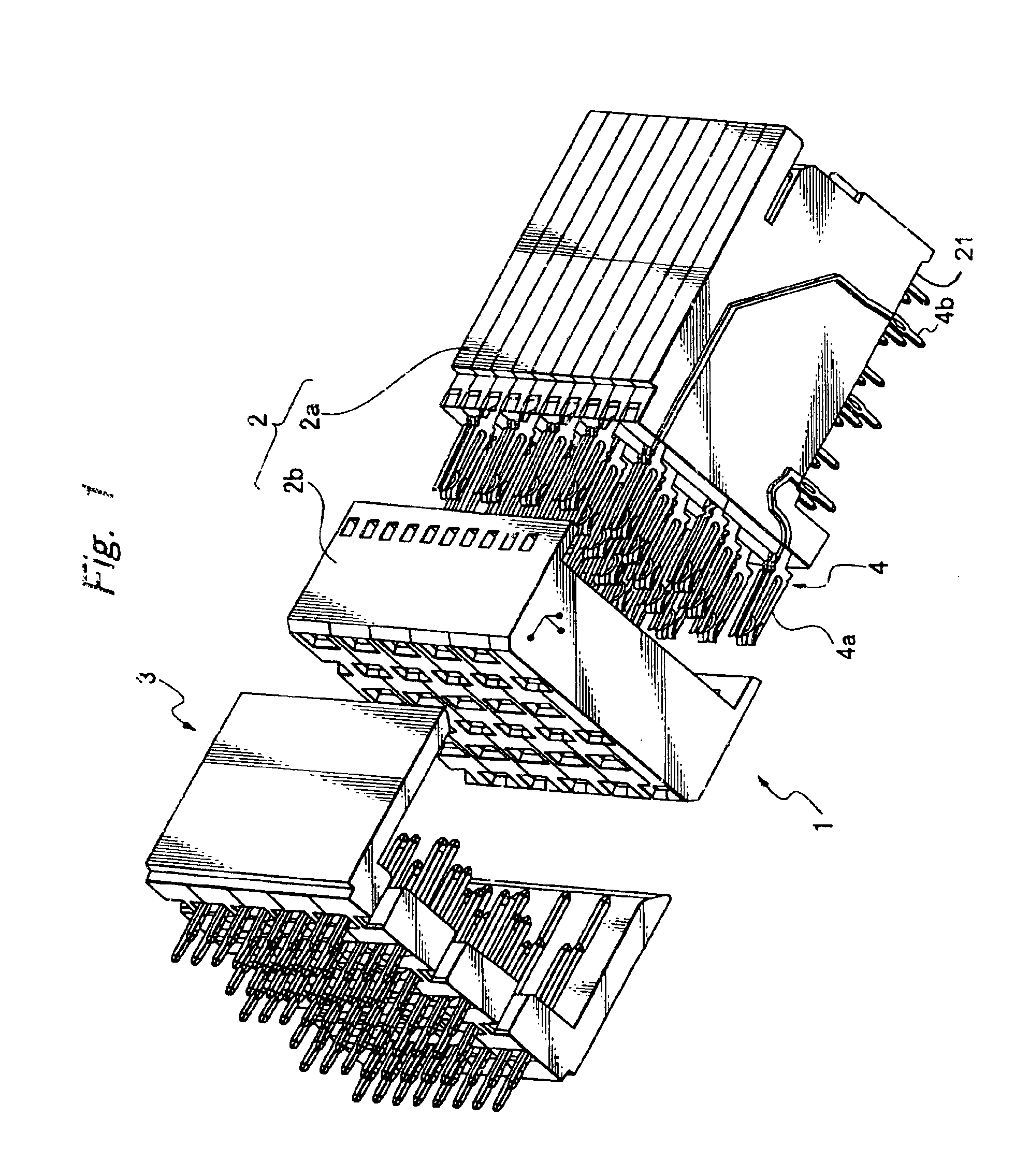
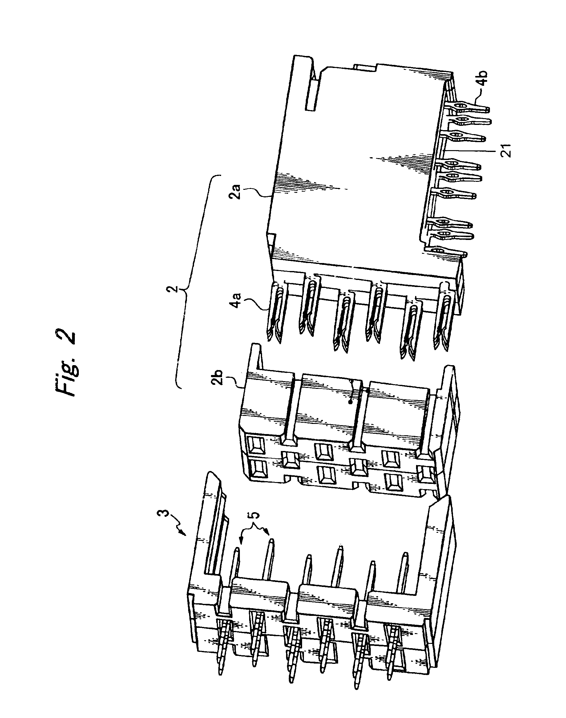
Referring to FIG. 1, an electric connector 1 comprises a female package part 2 and a male package part 3. The female package part 2 comprises a rectangular block 2a and a detachable rectangular insulating housing 2b to be fitted on the front side of the rectangular block 2a. The male package part 3 is a “U”-shaped cover to be applied to the rectangular insulating housing 2b.

The rectangular block (terminal mounting blocks) 2a has a raised bottom surface 21 to be laid on an associated printed circuit board. The rectangular insulating housing 2b has female slots arranged in a lattice form. Likewise, the “U”-shaped cover 3 has slots arranged in the same lattice pattern as the rectangular insulating housing 2b.

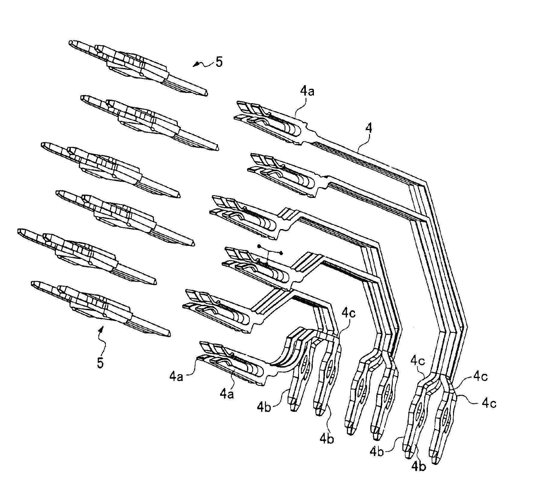
Referring to FIG. 4(A), each female contact piece (signal terminal) 4 is composed of a bifurcate contact end 4a, a non-bifurcate contact end 4b directed perpendicular to the bifurcate contact end 4a, and a curved or bent stem integrally connected at its opposite ends both to the ...


PUM


Abstract

An electric connector includes an insulating housing having slots arranged crosswise in vertical columns and horizontal lines, and signal terminals received in the slots. The signal terminals are paired to be received in each and every slot. The slots are staggered in vertical columns. The slots are so arranged that the ratio of “a” / “b” may be equal to or smaller than ⅓, where “a” stands for the distance between two signal terminals in each pair, and “b” stands for the distance between adjacent pair sets of signal terminals.

Description

BACKGROUND OF THE INVENTION1. Field of the InventionThe present invention relates to an electric connector for use in making a required electric connection between printed circuit boards, between a printed circuit board and a selected device in a computer, or between a printed circuit board and a server or backboard package, and more particularly to an electric connector for use in transmitting high-frequency signals.2. Related ArtReferring to FIG. 10, a conventional electric connector 11 has a plurality of pair sets of 12 signal terminals 12a and 12b for transmitting high-speed signals in differential transmission ways, thereby significantly reducing noise signals. More specifically, if cross talk appears between the pair of signal terminals 12a and 12b, unwanted signals of the same phase can be cancelled. Also, a ground terminal 13 is arranged between adjacent pair sets 12 of the signal terminals, thereby preventing cross talk from appearing in adjacent pair sets of signal termina...

Claims


Application Information

Patent Timeline
Patent Type & Authority Patents(United States)
IPC IPC(8): H01R12/16H01R12/00
CPCH01R23/688Y10S439/941H01R12/727H01R13/6585
Inventor OHNISHI, KOJIMATSUE, MASAHIKO
Owner HONDA TSUSHIN IND
Why Eureka
Try Eureka