Creeper with trays

Inactive Publication Date: 2006-08-03
WHITESIDE MFG
View PDF23 Cites 9 Cited by
  • Summary
  • Abstract
  • Description
  • Claims
  • Application Information

AI Technical Summary

Benefits of technology

[0010] In accordance with an additional aspect of the present invention, it is an object to provide

Problems solved by technology

One problem with these types of creepers is their stability.
That is, with the casters being oriented longitudinally aligned with each other on the side rails, a shifting of the weight of the user could cause a tipping of the creeper.
Another drawback of the creepers with these types of frames is that the crossmembers can interfere with the ability of the user

Method used


Image

  • Creeper with trays
  • Creeper with trays
  • Creeper with trays

Examples


Example

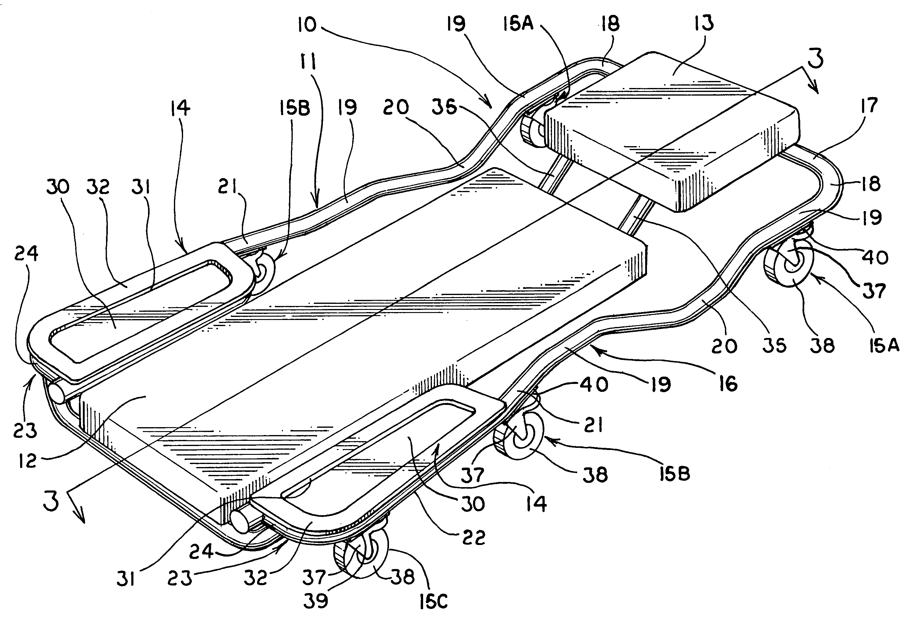
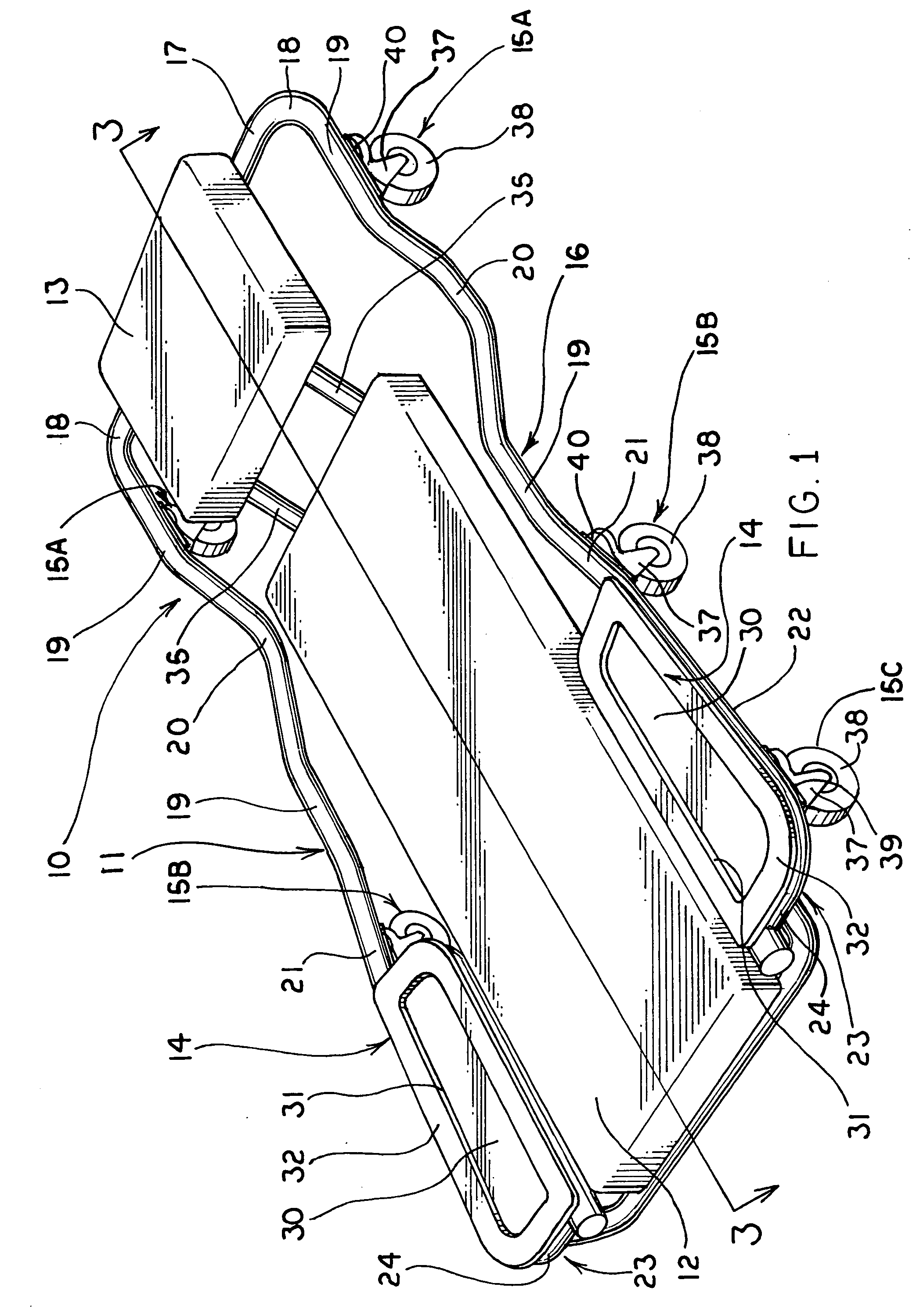
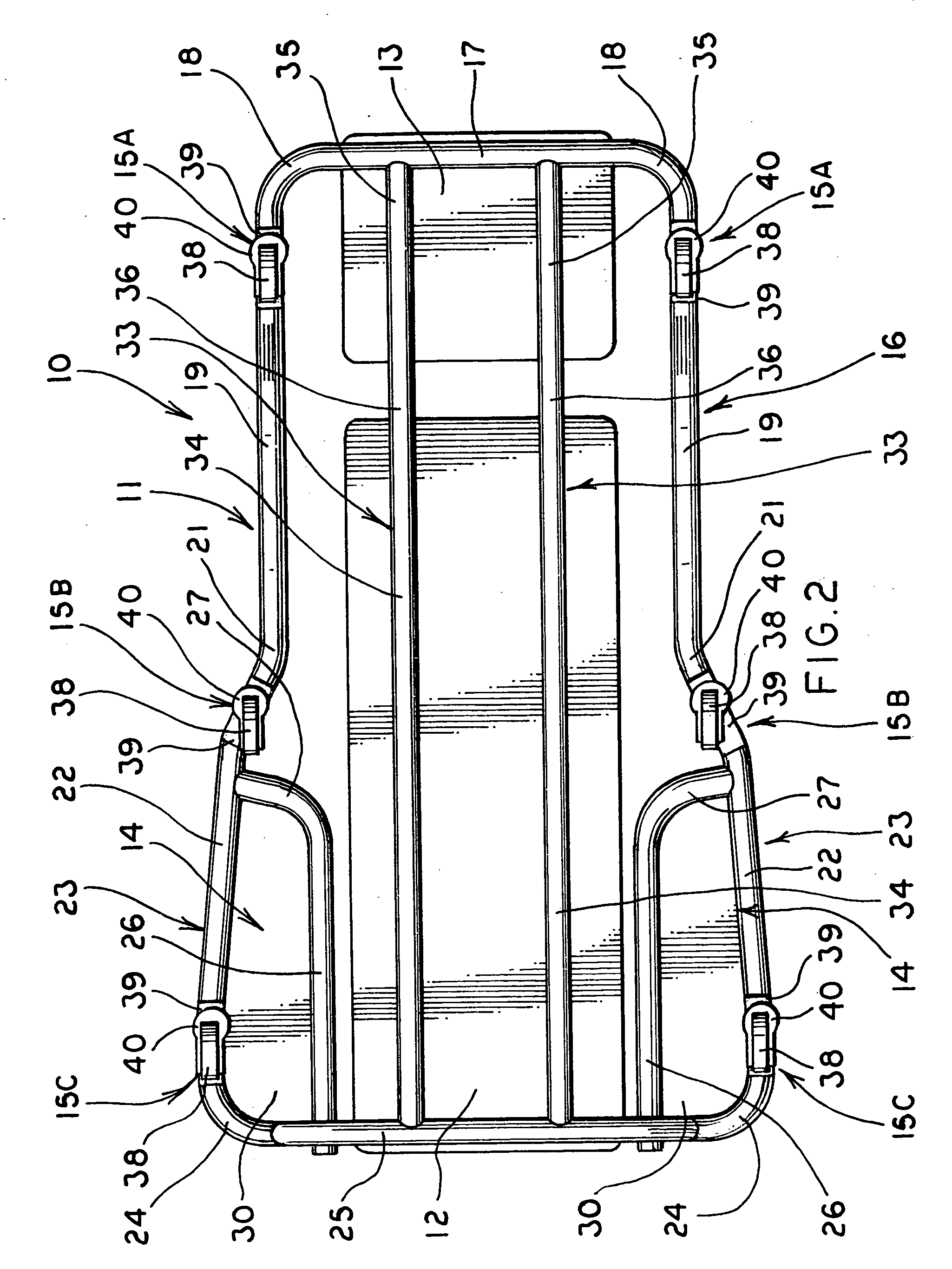
[0017] A mechanic's creeper made in accordance with the concepts of the present invention is generally indicated by the numeral 10. Creeper 10 includes a frame, generally indicated by the numeral 11, a body pad 12, a headrest pad 13, trays generally indicated by the numeral 14, and a plurality of opposed pairs of caster assemblies generally indicated by the numerals 15A, 15B and 15C.

[0018] All of the components of frame 11 are preferably circular or tubular in configuration and include a continuous main outer frame, generally indicated by the numeral 16. Outer frame 16 includes a laterally extending end member 17 positioned generally under and supporting the longitudinal end of headrest pad 13. The lateral ends of member 17 are formed as elbows 18 such that outer frame 16 turns approximately ninety degrees. Longitudinally extending, laterally spaced side rails 19 extend from the other end of elbows 18. Side rails 19 are generally straight, as viewed in plan in FIG. 2, but as shown ...


PUM


Abstract

A creeper (10) includes an outer frame (16) including side rails (19) and end members (17, 25). Support rails (33) extend longitudinally between the end members (17, 25), and they carry a headrest pad (13) and a body pad (12). There are no lateral supports between the side rails (19). Tray frames (23) carry trays (14) within the profile of the outer frame (16). A plurality of laterally opposed, longitudinally spaced, pairs of caster assemblies (15A, B, C) are carried by the side rails (19) and each pair is laterally spaced differently than the other pairs.

Description

CROSS-REFERENCE TO RELATED APPLICATION [0001] This application claims the benefit of U.S. Provisional Application No. 60 / 649,160 filed on Feb. 3, 2005.TECHNICAL FIELD [0002] This invention relates to a mechanic's creeper. More particularly, this invention relates to a creeper which has a frame with a wider wheel base, which has no crossmembers, and which can carry trays within the profile of the frame as viewed in plan view. BACKGROUND ART [0003] Typical mechanic's creepers include a frame having parallel, longitudinally extending side rails that carry casters which render the creeper mobile. The side rails are interconnected at their ends and also by a plurality of laterally extending, longitudinally spaced crossmembers which hold a pad which supports the body of the user of the creeper. The pad is usually provided with a thickened area which serves as a headrest. [0004] One problem with these types of creepers is their stability. That is, with the casters being oriented longitudin...

Claims


Application Information

Patent Timeline
IPC IPC(8): B25H5/00
CPCB25H5/00
Inventor WHITESIDE, KIRT E.OBITTS, SHANE
Owner WHITESIDE MFG
Why Eureka
Try Eureka