Voltage compensating circuit for a sensorless type DC brushless motor

Active Publication Date: 2006-07-06
IND TECH RES INST
View PDF5 Cites 0 Cited by
  • Summary
  • Abstract
  • Description
  • Claims
  • Application Information

AI Technical Summary

Benefits of technology

[0017] It is another objective of the present invention to provide a compensating circuit for promoting the stability of a sensorless DC brushless motor.
[00

Problems solved by technology

The induced potential obtained by the indirection induced potential detection has some problems, including a low noise ratio and delay; hence, the position of the armature cannot be precisely determined.
But an error will be caused by the voltage drops on the switch and

Method used


Image

  • Voltage compensating circuit for a sensorless type DC brushless motor
  • Voltage compensating circuit for a sensorless type DC brushless motor
  • Voltage compensating circuit for a sensorless type DC brushless motor

Examples


Example

[0023] Reference will now be made in detail to the present preferred embodiments of the invention, examples of which are illustrated in the accompanying drawings. Wherever possible, the same reference numbers are used in the drawings and the description to refer to the same or like parts.

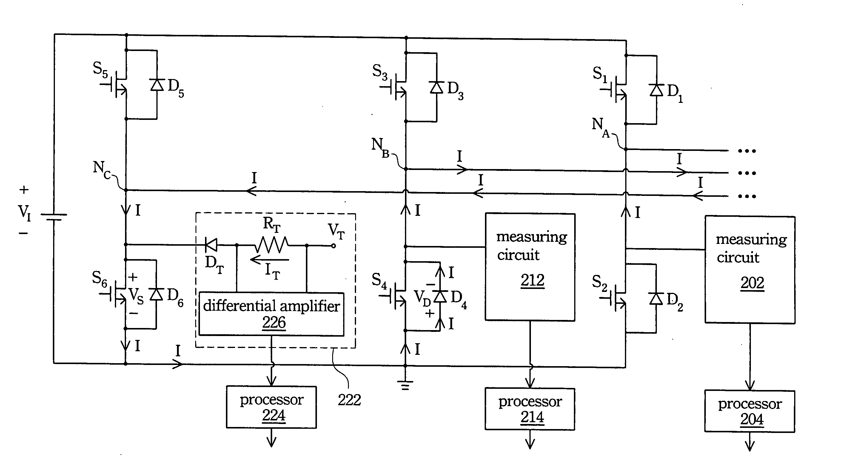
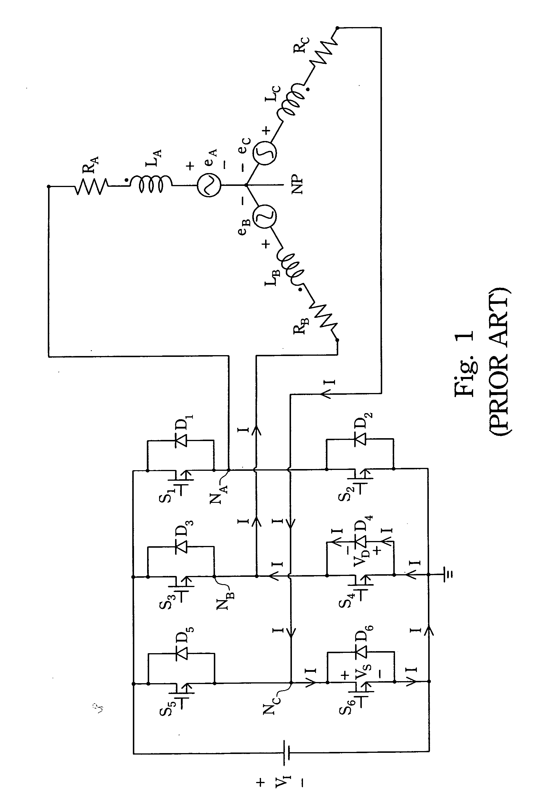
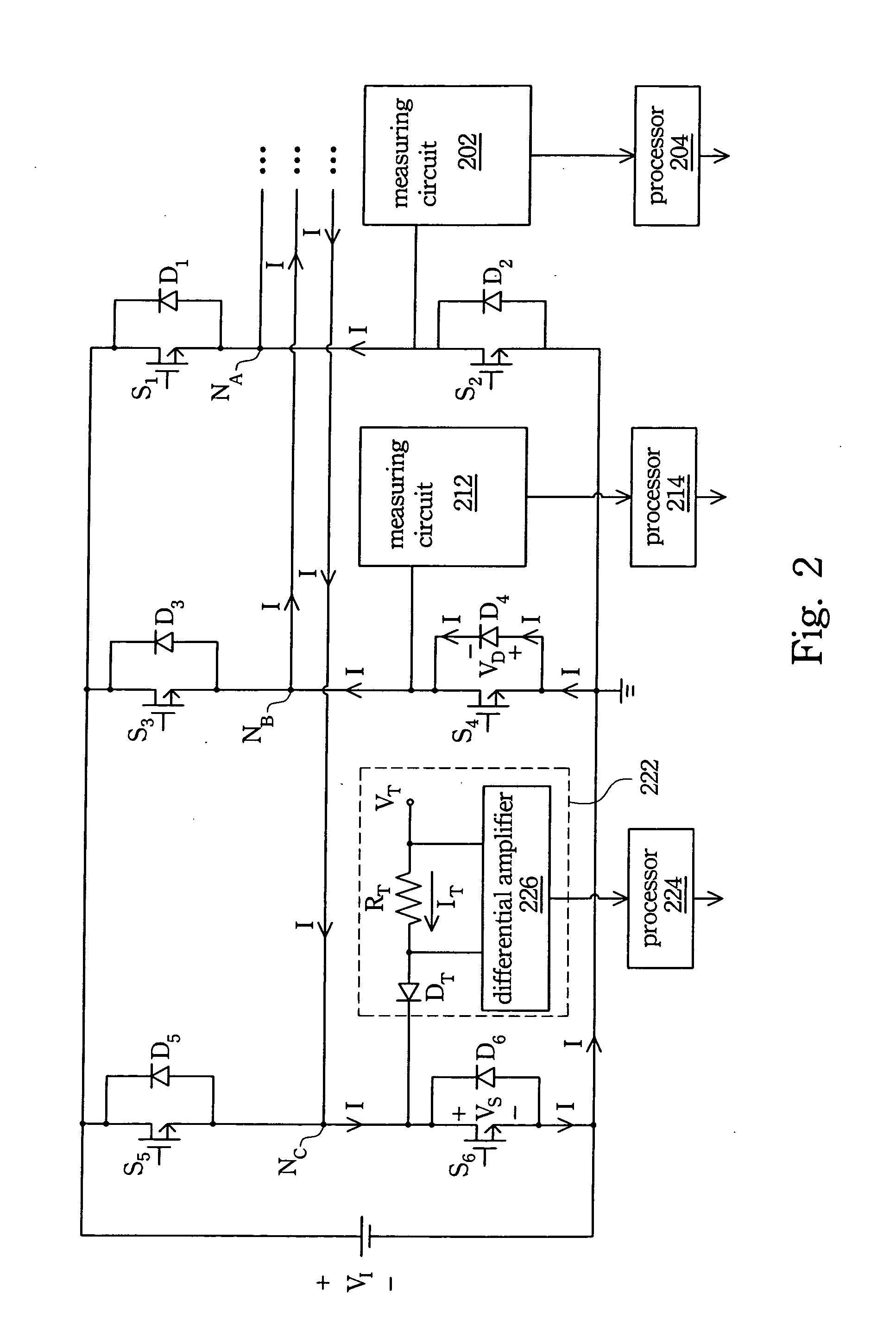
[0024] In the conventional sensorless DC brushless motor, a voltage with an error, which is (VS−VD) / 2, is easily obtained by using direct induced potential detection to detect the position of the armature in the motor, where the voltages VS and VD are voltage drops at a switch device and a diode device, respectively, when an induced current passes through the driving motor. The voltage VS varies with the magnitude of the induced current; therefore, the compensating circuit according to the embodiment of the present invention comprises two parts, a measuring circuit used to measure the real error parameter, and a processing circuit used to carry out the computing and compensating operation.

[0025]FI...


PUM


Abstract

A compensating circuit for compensating the terminal voltage on the armature in a sensorless type DC brushless motor apparatus is described. The driving circuit of the motor apparatus outputs a three-phase power, and each phase is connected with a compensating circuit. The compensating circuit has a reference voltage, a resistance device, a diode device, a differential amplifier and a processor. The two terminals of the resistance device are respectively connected to the reference voltage and the anode of the diode device. The cathode of the diode device is connected to an output of the three-phase power supply. The two input terminals of the differential amplifier are respectively connected to the two terminals of the resistance device. The processor accepts the signal output from the differential amplifier and then calculates and outputs a compensating voltage.

Description

RELATED APPLICATIONS [0001] The present application is based on, and claims priority from, Taiwan Application Serial Number 93141807, filed Dec. 31, 2004, the disclosure of which is hereby incorporated by reference herein in its entirety. BACKGROUND [0002] 1. Field of Invention [0003] The present invention relates to a voltage compensating circuit. More particularly, the present invention relates to a voltage compensating circuit for a sensorless type DC brushless motor. [0004] 2. Description of Related Art [0005] In the field of motors, the three-phase brushless motor is a kind of motor apparatus with high power efficiency; moreover, the volume thereof can be reduced more easily than that of other kinds of motor. Therefore, the DC brushless motor is well suited to every kind of 3C production and is now in widespread use. [0006] The three-phase DC brushless motor is a kind of electrical commutation motor (ECM). The basic design of the three-phase DC brushless motor is determining th...

Claims


Application Information

Patent Timeline
IPC IPC(8): H02P7/06
CPCH02P6/182
Inventor YANG, MING-CHEHUANG, TAI-MINGCHEN, CHIH-HSINCHEN, MU-PINGFANG, CHIH-HSINGHWU, KUO-ING
Owner IND TECH RES INST
Why Eureka
Try Eureka