Magnetic sensor with tilted magnetoresistive structures

a magnetoresistive structure and magnetic sensor technology, applied in the field of magnetic sensor and magnetic sensor device, can solve the problems of inherently insufficient determination of absolute direction of multilayer elements, cost-intensive manual positioning and orienting of various magnetoresistive elements, and insufficient magnetic field

Inactive Publication Date: 2006-08-03
IBM CORP
View PDF8 Cites 33 Cited by
  • Summary
  • Abstract
  • Description
  • Claims
  • Application Information

AI Technical Summary

Problems solved by technology

Due to the symmetry of their underlying physical effects magnetoresistive multilayer elements inherently do not provide determination of the absolute direction of a magnetic field.
However, by combining numerous magnetoresistive spinvalve elements, e.g. such as in a Wheatstone bridge, in principle also the direction of a magnetic field can be unequivocally determined.
However, for various magnetic field sensor applications a manual positioning and orienting of various magnetoresistive elements is rather cost intensive and may reduce measurement accuracy of the magnetic sensor device.
Also, magnetic sensors making use of magnetoresistive elements are commonly only sensitive to magnetic fields that coincide with the plane of the layered structures.

Method used


Image

  • Magnetic sensor with tilted magnetoresistive structures
  • Magnetic sensor with tilted magnetoresistive structures
  • Magnetic sensor with tilted magnetoresistive structures

Examples


Embodiment Construction

[0024] The following description is the best mode presently contemplated for carrying out the present invention. This description is made for the purpose of illustrating the general principles of the present invention and is not meant to limit the inventive concepts claimed herein. Further, particular features described herein can be used in combination with other described features in each of the various possible combinations and permutations.

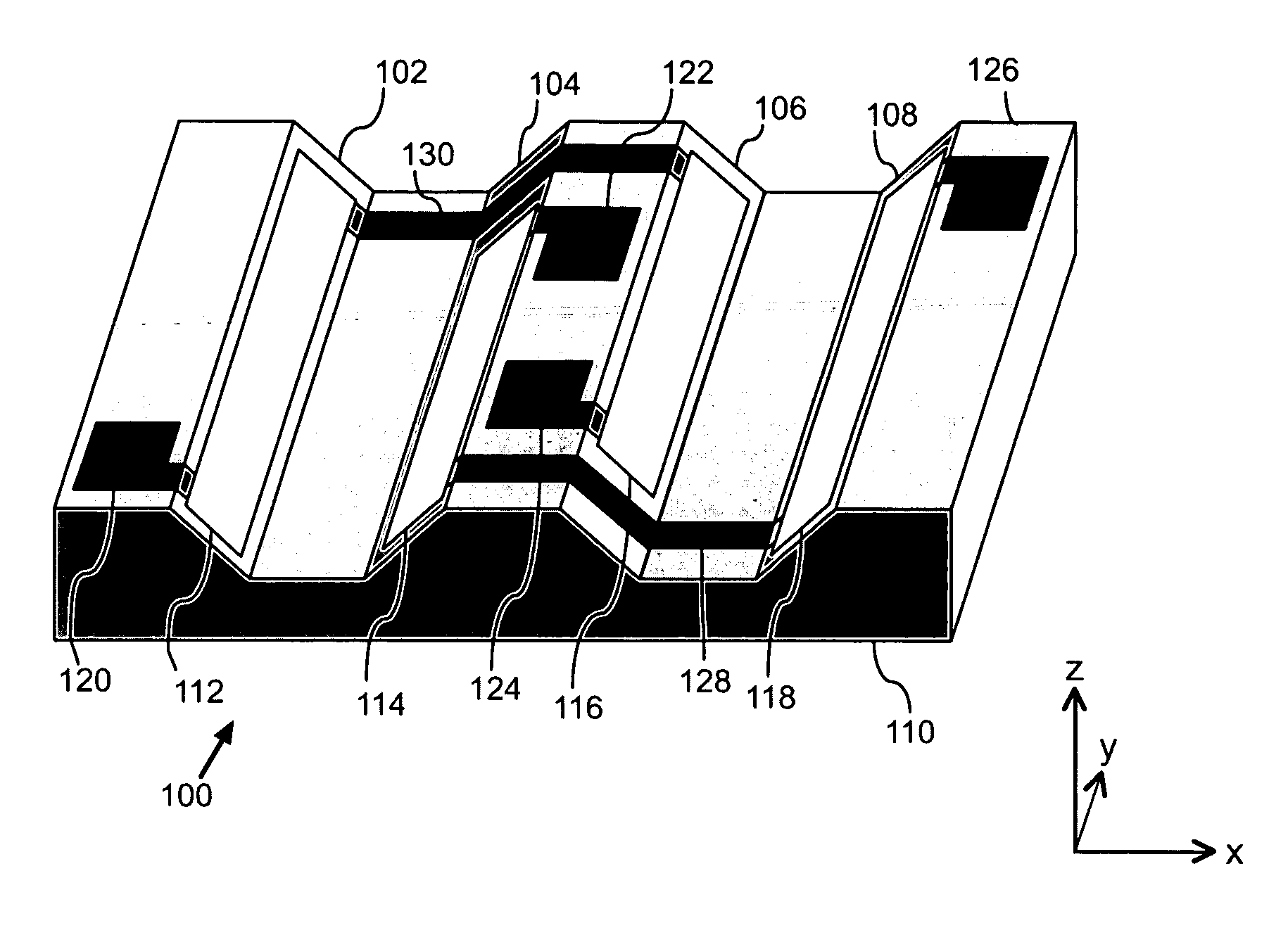
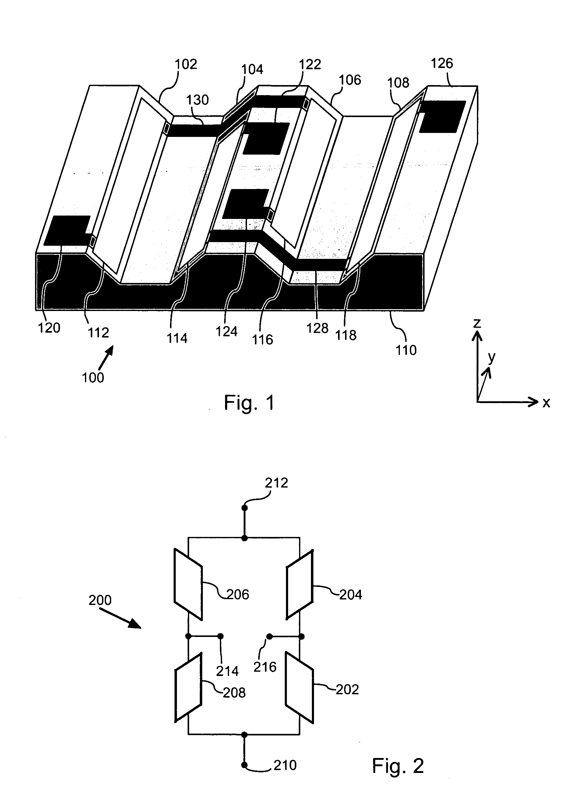
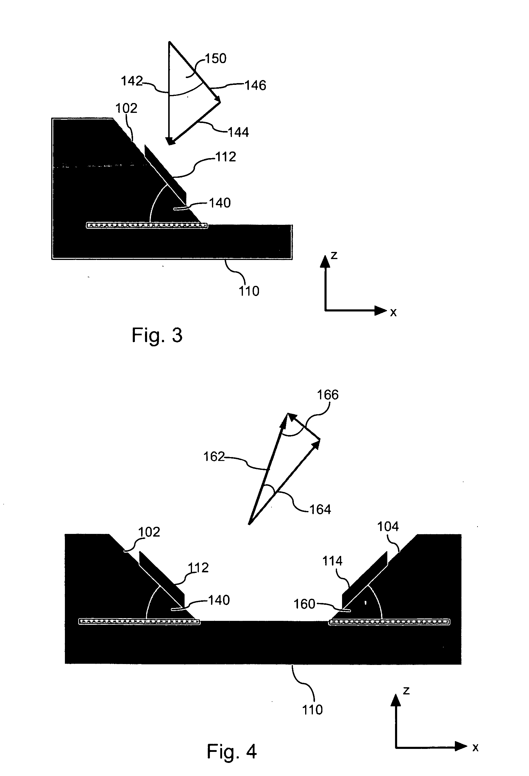
[0025]FIG. 1 is illustrative of a perspective view of the magnetic field sensor device 100. Magnetic field sensor device 100 has a planar substrate 110 featuring two parallel oriented grooves. The two grooves have side walls acting as tilted planar sections and providing a basis for deposition of magnetoresistive layered structures. In particular, the planar substrate has one or more tilted planar sections 102, 104, 106 and 108 (four tilted planar sections shown), wherein planar sections 102 and 106 are oriented in the same parallel way. Simi...


PUM

PropertyMeasurementUnit
relative angleaaaaaaaaaa
surface normalaaaaaaaaaa
magnetoresistiveaaaaaaaaaa

Abstract

A magnetic field sensor device comprising a substrate having at least a first tilted planar section having a surface normal at a first angle with respect to a surface normal of the substrate, and at least a first magnetoresistive layered structure positioned at the at least first tilted section. Methods for manufacturing magnetic field sensor devices are also presented.

Description

FIELD OF THE INVENTION [0001] The present invention relates to the field of magnetic sensors and magnetic sensor devices making use of magnetoresistive structures and in particular without limitations to magnetoresistive layered structures having an electric resistance that depends on an applied magnetic field. [0002] BACKGROUND AND PRIOR ART [0003] Magnetoresistive elements feature an electrical resistance that strongly depends on the magnitude and / or a direction of an externally applied magnetic field. By means of magnetoresistive elements, electrical signals can be generated that are indicative of magnetic field strength and / or direction. These elements are therefore suitable for a large range of applications in the framework of magnetic field measuring and determination. In particular in applications for touch less measuring of rotation angles and revolution speeds, magnetic sensors making use of magnetoresistive elements play a predominant role. Also, magnetoresistive elements ...

Claims


Application Information

Patent Timeline
Patent Type & Authority Applications(United States)
IPC IPC(8): G11B5/33G11B5/127
CPCG01R33/0206G11B5/3909G11B5/3951G11B2005/3996
Inventor BRCUER, MARCUSCROLLY, GUENTHERHAAG, MICHAELJUNG, MANFREDMUEHGE, THORSTENPAUL, JOHANNESSAUERWEIN, JOERGSCHAEFER, ROLFWELZEL, ALEXANDRA
Owner IBM CORP
Why Eureka
Try Eureka