Loading, unloading and refrigeration apparatus for refrigerated trailers

a trailer and refrigeration technology, applied in the field of trailer loading and unloading, can solve the problems of reducing the insulation effect of trailers, affecting the efficiency of insulation,

Inactive Publication Date: 2006-08-17
ORLANDO ANTHONY D
View PDF14 Cites 13 Cited by
  • Summary
  • Abstract
  • Description
  • Claims
  • Application Information

AI Technical Summary

Benefits of technology

[0017] Preferably, the refrigerated trailer further includes a refrigeration unit and a pair of ventilation ducts in communication with the refrigeration unit to provide refrigerated air from the refrigeration unit to the rear of the trailer, with one of the pair of ventilation ducts disposed along the ceiling adjacently to one sidewall of the trailer and the other of the pair of ventilation ducts disposed along the ceiling adjacently to the other sidewall of the trailer to provide maximum floor to ceiling height in a central area of the refrigerated trailer.
[0018] Yet another aspect of the present invention includes a refrigeration system for a refrigerated trailer, the refrigeration system including a refrigeration unit and a pair of ventilation ducts in communication with the refrigeration unit to provide refrigerated air from the refrigeration unit to the rear of the trailer, with one of the pair of ventilation ducts disposed along the ceiling adjacently to one sidewall of the trailer and the other of the pair of ventilation ducts disposed along the ceiling adjacently to the other sidewall of the trailer to provide maximum floor to ceiling height in a central area of the refrigerated trailer.

Problems solved by technology

However, such roller tracks have not been employed in refrigerated semi-trailers.
Otherwise, the refrigeration qualities or characteristics of the trailer may be compromised by air leakage.
Furthermore, a puncture in the floor may also cause moisture drainage to infiltrate the insulation, thereby reducing the effectiveness of the insulation.
This centrally located ventilation duct limits the effective floor to ceiling height in refrigerated trailers.

Method used


Image

  • Loading, unloading and refrigeration apparatus for refrigerated trailers
  • Loading, unloading and refrigeration apparatus for refrigerated trailers
  • Loading, unloading and refrigeration apparatus for refrigerated trailers

Examples


Embodiment Construction

[0027] It will be understood that the invention may be embodied in other specific forms without departing from the spirit thereof. The present examples and embodiments, therefore, are to be considered in all respects as illustrative and not restrictive, and the invention is not to be limited to the details given herein.

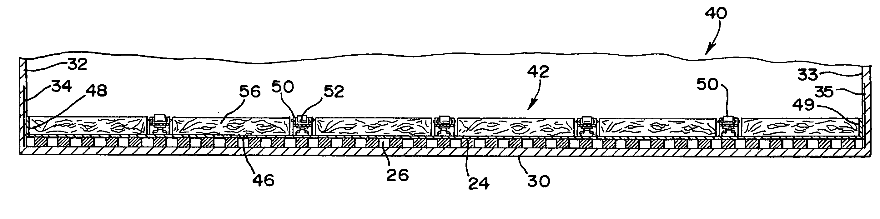
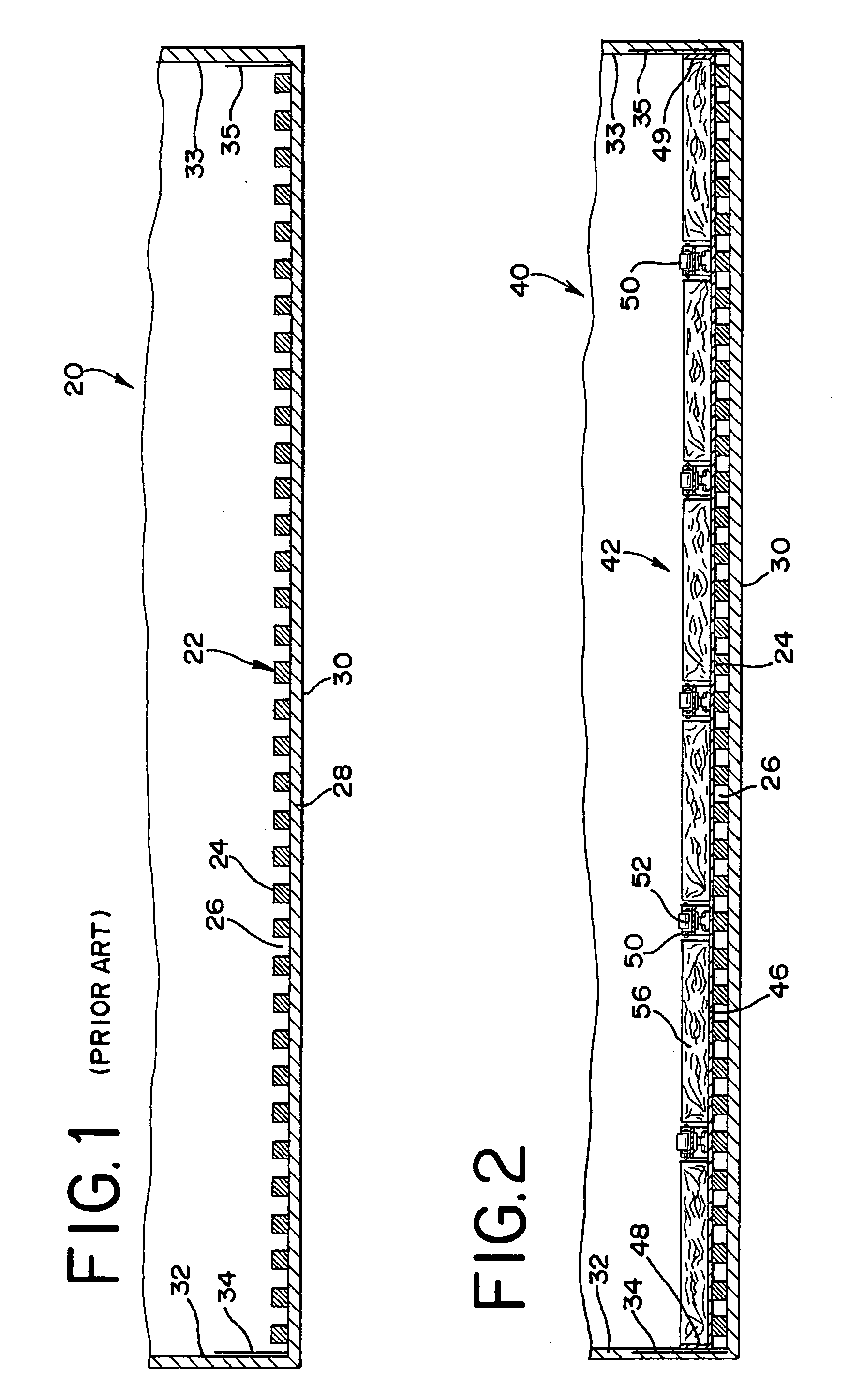
[0028] With reference to the drawing Figures, FIG. 1 illustrates a transverse cross-sectional view of a prior art floor, generally designated 22, disposed in a lower portion of a refrigerated trailer, generally designated 20. Floor 22 typically consists of a plurality of spaced-apart ribs 24 that generally extend longitudinally the length of floor 22. For example, ribs 24 may each be about 2 inches (about 5 cm) by 2 inches in cross-sectional dimension with a gap 26 of about 2 inches (about 5 cm) in width disposed between adjacent ribs 24. Gaps 26 permit refrigerated air to flow underneath any skids, pallets, containers, or the like, that set upon the upper surface of...


PUM


Abstract

Loading and unloading apparatus for a refrigerated trailer including a floor with a plurality of ribs extending longitudinally along the floor of the refrigerated trailer with a gap between adjacently disposed ribs, a sub floor disposed over the floor and the longitudinally extending ribs; a plurality of roller tracks disposed on the sub floor, the roller tracks extending longitudinally in the trailer and spaced apart from each other and a plurality of sleepers, the sleepers disposed longitudinally in the trailer and generally parallel with the roller tracks, with at least one of the plurality of sleepers disposed between adjacently disposed roller tracks. Preferably, a refrigeration unit has bifurcated ducts located along the ceiling adjacent to the sidewalls to preserve ceiling height.

Description

FIELD OF THE INVENTION [0001] The present invention relates generally to apparatus for the handling of cargo, and more particularly apparatus for loading and unloading of refrigerated trailers. The present invention also relates to refrigeration apparatus for refrigerated trailers. BACKGROUND OF THE INVENTION [0002] Roller systems have previously been employed in trailers of the type that are commonly called semi-trailers that are attached to, and moved by, semi-trucks. Such roller systems are typically used to move cargo that is placed on pallets, skids, containers, or the like. For example, U.S. Pat. No. 4,089,399 to Webb discloses pneumatically actuated roller tracks for load handling. These roller tracks include a plurality of rollers that can be pneumatically actuated by an inflatable bladder to rise partially above the top surface of the track. Loads can then be moved along the raised rollers to a desired position in the trailer. When the bladder is deflated, the rollers will ...

Claims


Application Information

Patent Timeline
Patent Type & Authority Applications(United States)
IPC IPC(8): B60P1/00
CPCB60H1/00014B60P1/52B60P3/20B62D25/2054B62D33/048B60H2001/003B60H1/00295
Inventor ORLANDO, ANTHONY D.
Owner ORLANDO ANTHONY D
Why Eureka
Try Eureka