
Laryngoscope

a technology of laryngoscope and ophthalmology, which is applied in the field of laryngoscope, can solve the problems of cosmetic disfigurement, extensive restoration dentistry, and damage to the teeth of patients, and achieve the effects of reducing the risk of ophthalmology, and improving the quality of ophthalmology

Inactive Publication Date: 2006-08-17
HOWARD GREGORY L
View PDF40 Cites 32 Cited by
  • Summary
  • Abstract
  • Description
  • Claims
  • Application Information

AI Technical Summary

Benefits of technology

[0009] In one embodiment, a laryngoscope is used with a conventional handle for manipulating a laryngoscope blade. The handle may be a generally cylindrical member having a handle axis. The elongate laryngoscope blade is manipulated by the handle for insertion into the patient, and includes a curved or a straight blade axis lying within the blade axis plane. A connecting member, which may be in the form of a rigid shaft, interconnects the blade and the handle. The handle axis is laterally spaced from the blade axis plane by a s

Problems solved by technology

A common complaint of the laryngoscope involves damage to the teeth of the patient.
Not only may there be cosmetic disfigurement, but discomfort and extensive restoration dentistry.
If a patient aspirates a dislodged tooth or fragment, there may be pulmonary complications.
Some prior art devices have a connecting member between the molars, but the handle configuration does not allow for force to be applied to the molars during difficult intubation.

Method used


Image

  • Laryngoscope
  • Laryngoscope
  • Laryngoscope

Examples


Embodiment Construction

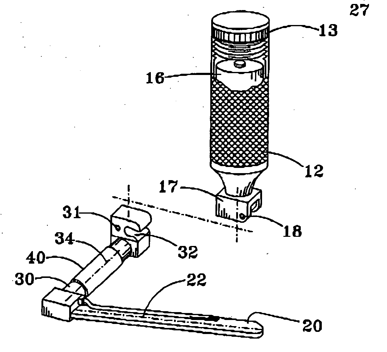
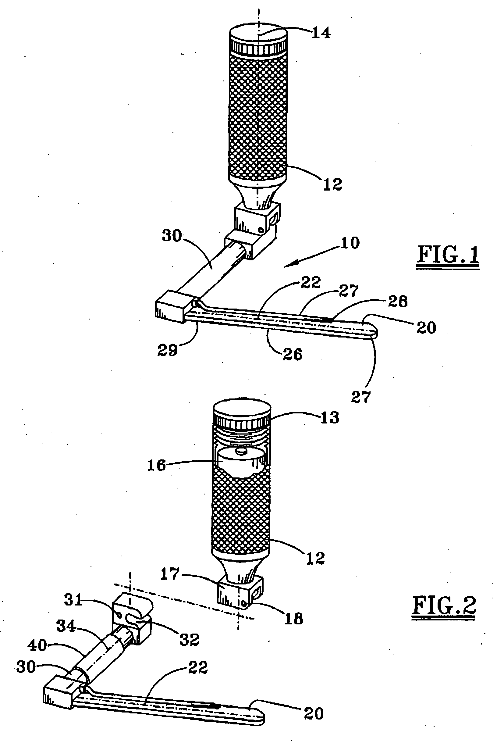
[0013] Referring to FIG. 1, the laryngoscope 10 includes a conventional handle 12 having a generally cylindrical configuration for manipulating the laryngoscope blade 20. The handle 12 includes a handle axis 14, and conventionally includes a battery or other power source 16 (see FIG. 2) for illuminating an area adjacent the blade. An end cap 13 may be removed from the body of the handle to obtain access to the interior of the handle.

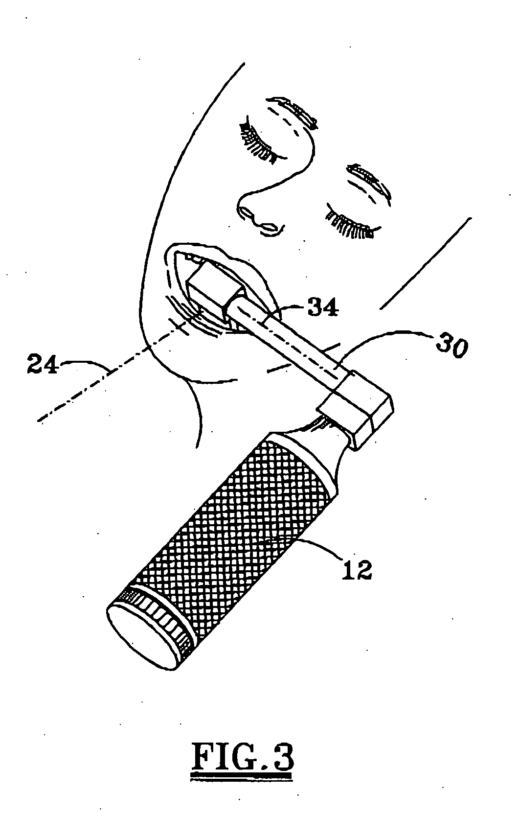
[0014] The elongate blade 20 is configured for insertion into the patient, and may have a relatively straight axis or a curved axis. In either event, the elongate blade axis 22 lies within a blade axis plane 24 (see FIG. 3) which is in use generally centered with respect to the mouth and throat of the patient. The configuration of the blade will depend on the desires of the practitioner and the physical characteristics of the patient. A substantially straight blade is shown in FIG. 1, although a blade with a curved axis may be used. The blade 20 general...


PUM


Abstract

A laryngoscope 10 includes an elongate blade 20 for insertion into the patient, a handle 12 for manipulating the blade, and a connecting member 30 interconnecting the blade and the handle. The handle axis 14 is laterally spaced from a plane of a blade axis 22 such that the handle is exterior of the patient's mouth when manipulating the blade. In one embodiment, the connecting member 30 has a connecting member axis 34 angled at about 90° relative to the plane of the blade axis 22. The laryngoscope blade is removably connected to the handle, and is fixably secured to the blade.

Description

FIELD OF THE INVENTION [0001] The present invention relates to a laryngoscope suitable for tracheal intubation of patients. The laryngoscope may be used to visualize the laryngeal area of the body, and significantly reduces the likelihood of damage to the patient's teeth. BACKGROUND OF THE INVENTION [0002] Laryngoscopes are commonly used to facilitate endotracheal intubation during surgery to permit the patient to breathe and / or to administer anaesthesia. The patient's head is conventionally tilted backwards as far as possible and the lower jaw distended to open the mouth widely. A rigid blade, which may be straight or curved, may be inserted through the mouth into the throat passageway to expose the glottis. [0003] There are many types of laryngoscope blades. Many have a channel along the blade to help guide the endotracheal tube during insertion into the larynx. Some blades have complex contours and shapes. The laryngoscope blade is preferably rigid, durable and sterilizable. To a...

Claims


Application Information

Patent Timeline
IPC IPC(8): A61B1/267
CPCA61B1/267
Inventor HOWARD, GREGORY L.
Owner HOWARD GREGORY L
Learn More