Method and apparatus for measuring optical density of image printed on medium

a technology of optical density and image, which is applied in the field of method and apparatus for measuring the optical density of an image printed on a medium, can solve the problems of undesirable additional costs and inability to print images in the same color by image forming apparatuses of the same type,

Inactive Publication Date: 2006-08-31
SAMSUNG ELECTRONICS CO LTD
View PDF0 Cites 1 Cited by
  • Summary
  • Abstract
  • Description
  • Claims
  • Application Information

AI Technical Summary

Benefits of technology

[0010] Embodiments of the present invention substantially solve the above and other problems, and provide a method and apparatus for measuring the optical density of an image printed on a medium by measuring the amount of light reflected from a medium using a sensor installed in an image forming apparatus.

Problems solved by technology

However, images printed in the same color by image forming apparatuses of the same type may not have the same optical density because of slight differences in the elements of the image forming apparatuses.
Conventionally, the optical density of an image printed on a medium is measured using an additional optical density measurement device, which undesirably incurs additional costs.

Method used


Image

  • Method and apparatus for measuring optical density of image printed on medium
  • Method and apparatus for measuring optical density of image printed on medium
  • Method and apparatus for measuring optical density of image printed on medium

Examples


Embodiment Construction

[0041] Embodiments of the present invention will now be described more fully with reference to the accompanying drawings in which exemplary embodiments of the invention are shown.

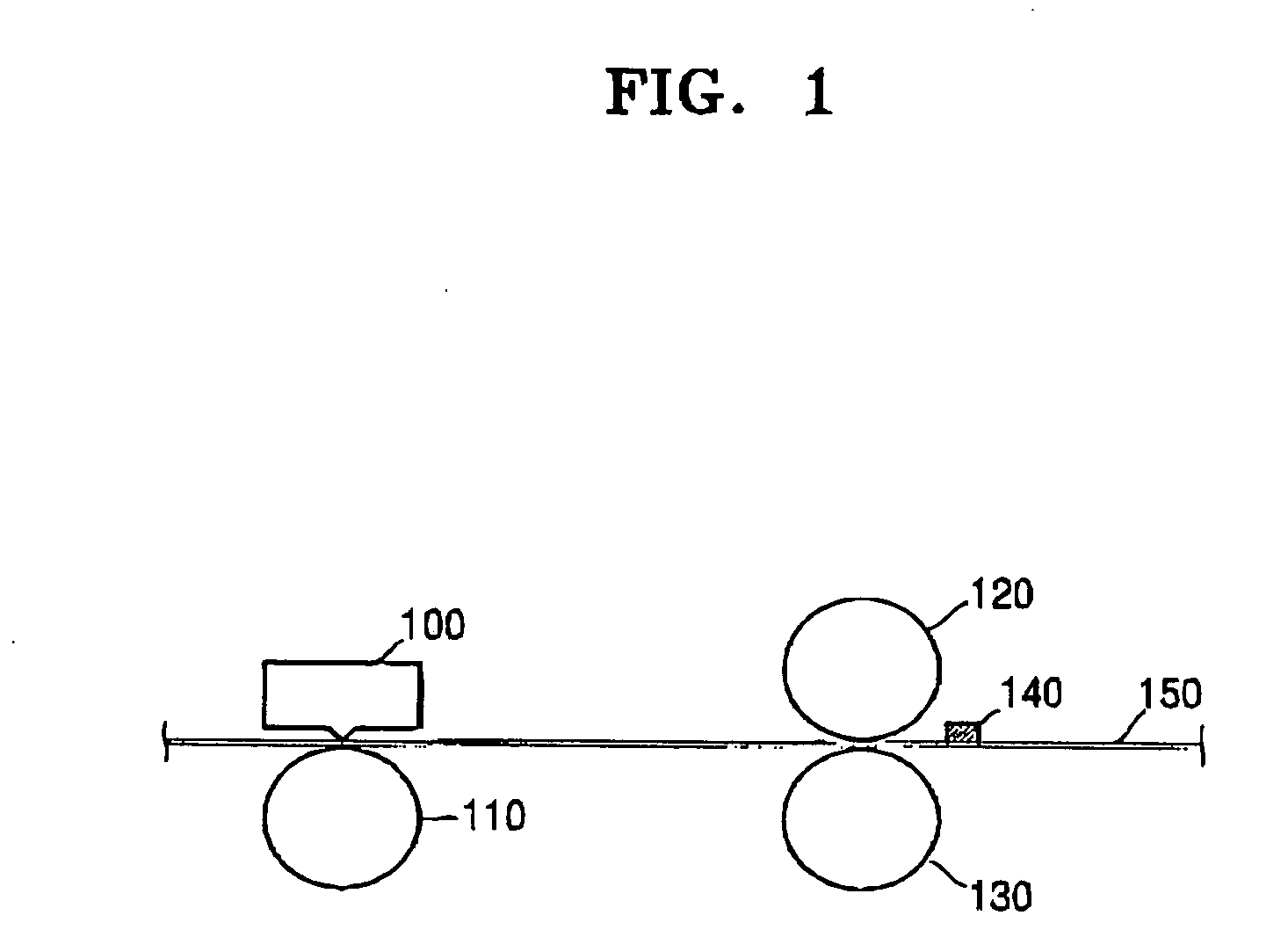
[0042]FIG. 1 is a perspective view illustrating an image forming apparatus using a method of measuring the optical density of an image printed on a medium according to an exemplary embodiment of the present invention. Referring to FIG. 1, the image forming apparatus comprises a thermal transfer head 100, a platen roller 110, a slave roller 120, a driving roller 130, and a sensor 140. The operation of the image forming apparatus will be described in greater detail below with reference to FIG. 9.

[0043] A printing method of the image forming apparatus will now be described in detail. The driving roller 130 transfers a medium 150 while rotating by engagement with a motor (not shown), which is a driving source. The slave roller 120 engages the driving roller 130 through the medium 150 located therebetween, and...


PUM


Abstract

A method and apparatus are provided for measuring the optical density of an image printed on a medium in an image forming apparatus. The method includes the steps of reading reference information from a memory, measuring the amount of light reflected from a medium on which a target image is printed by applying light to the medium, and calculating the optical density of the target image using the reference information and the measured amount of light reflected from the medium. Accordingly, it is possible to precisely measure the optical density of an image printed on the medium without the aid of an additional optical density measurement device and easily reduce differences or variations in the quality of printing between image forming apparatuses.

Description

CROSS-REFERENCE TO RELATED PATENT APPLICATION [0001] This application claims the benefit under 35 U.S.C. §119(a) of Korean Patent Application No. 10-2005-0016177, filed in the Korean Intellectual Property Office on Feb. 25, 2005, the entire disclosure of which is incorporated herein by reference. BACKGROUND OF THE INVENTION [0002] 1. Field of the Invention [0003] The present invention relates to a method and apparatus for measuring the optical density of an image printed on a medium in an image forming apparatus. More particularly, the present invention relates to a method and apparatus for measuring the optical density of an image printed on a medium by measuring the amount of light reflected from a medium and calculating the optical density of an image printed on the medium using the measured amount of light and an equation. [0004] 2. Description of the Related Art [0005] Generally, image forming apparatuses convert a document written by a user via an application program or an ima...

Claims


Application Information

Patent Timeline
IPC IPC(8): B41J2/36
CPCB41J2/36A47G9/0223A47G2009/001
Inventor KIM, HYOUNG-ILKANG, KYUNG-PYO
Owner SAMSUNG ELECTRONICS CO LTD
Why Eureka
Try Eureka