Lighting device, electro-optical device and electronic apparatus

a technology of electrooptical devices and light sources, applied in the field of light sources, can solve the problems of dispersed light source brightness and gap between light sources, and achieve the effect of preventing the brightness of light sources

Active Publication Date: 2006-09-14
BOE TECH GRP CO LTD
View PDF3 Cites 21 Cited by
  • Summary
  • Abstract
  • Description
  • Claims
  • Application Information

AI Technical Summary

Benefits of technology

[0009] An advantage of some aspects of the invention is to prevent the brightness of a light source from being dispersed by stopping the position of the ...

Problems solved by technology

In this case, there is a possibility that the brightness of the lighting device is dispersed.
In addition, since the size difference is shown betwe...

Method used


Image

  • Lighting device, electro-optical device and electronic apparatus
  • Lighting device, electro-optical device and electronic apparatus
  • Lighting device, electro-optical device and electronic apparatus

Examples


first embodiment

of Lighting Device and Electro-Optical Device

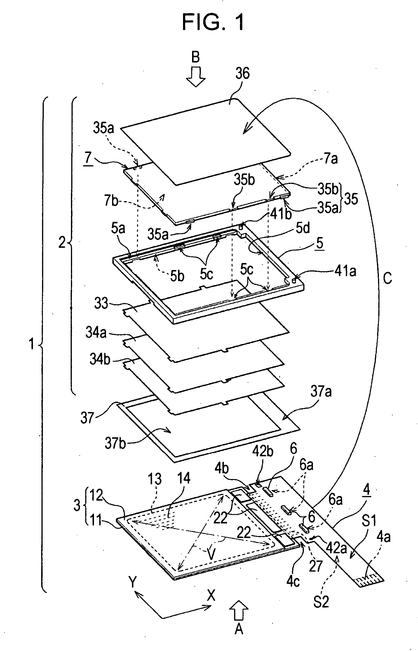
[0037] Hereinafter, the embodiment of the invention will be described with reference to applying the invention to the lighting device used for the electro-optical device. In addition, the embodiment described thereafter is an example, but is not limited to the invention. Besides, in further description, since the drawing is referenced at need, but the drawing indicates the important member in the configuration constituted by the plurality of members with ease, each member is indicated as relative size different from the reality.

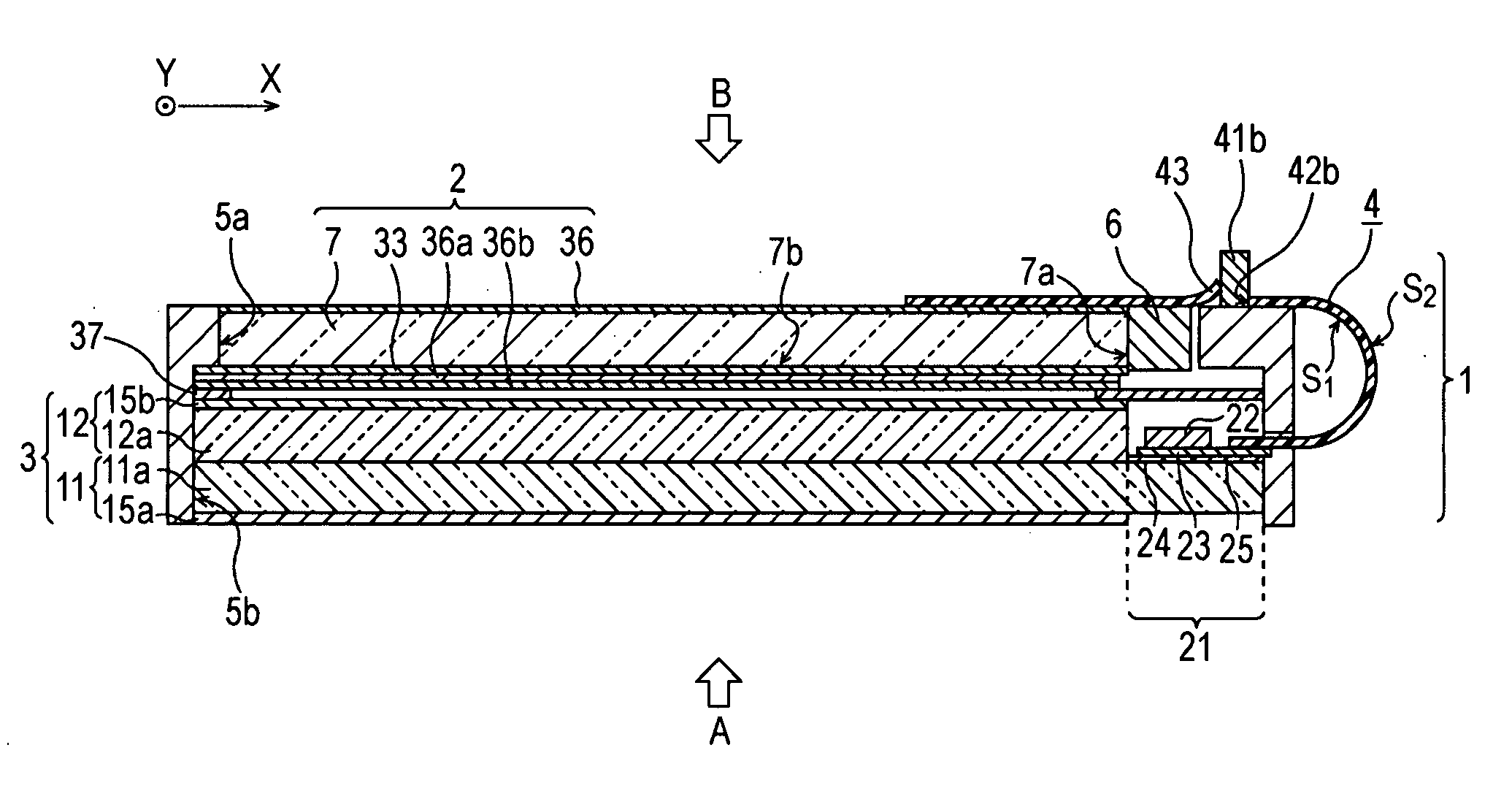
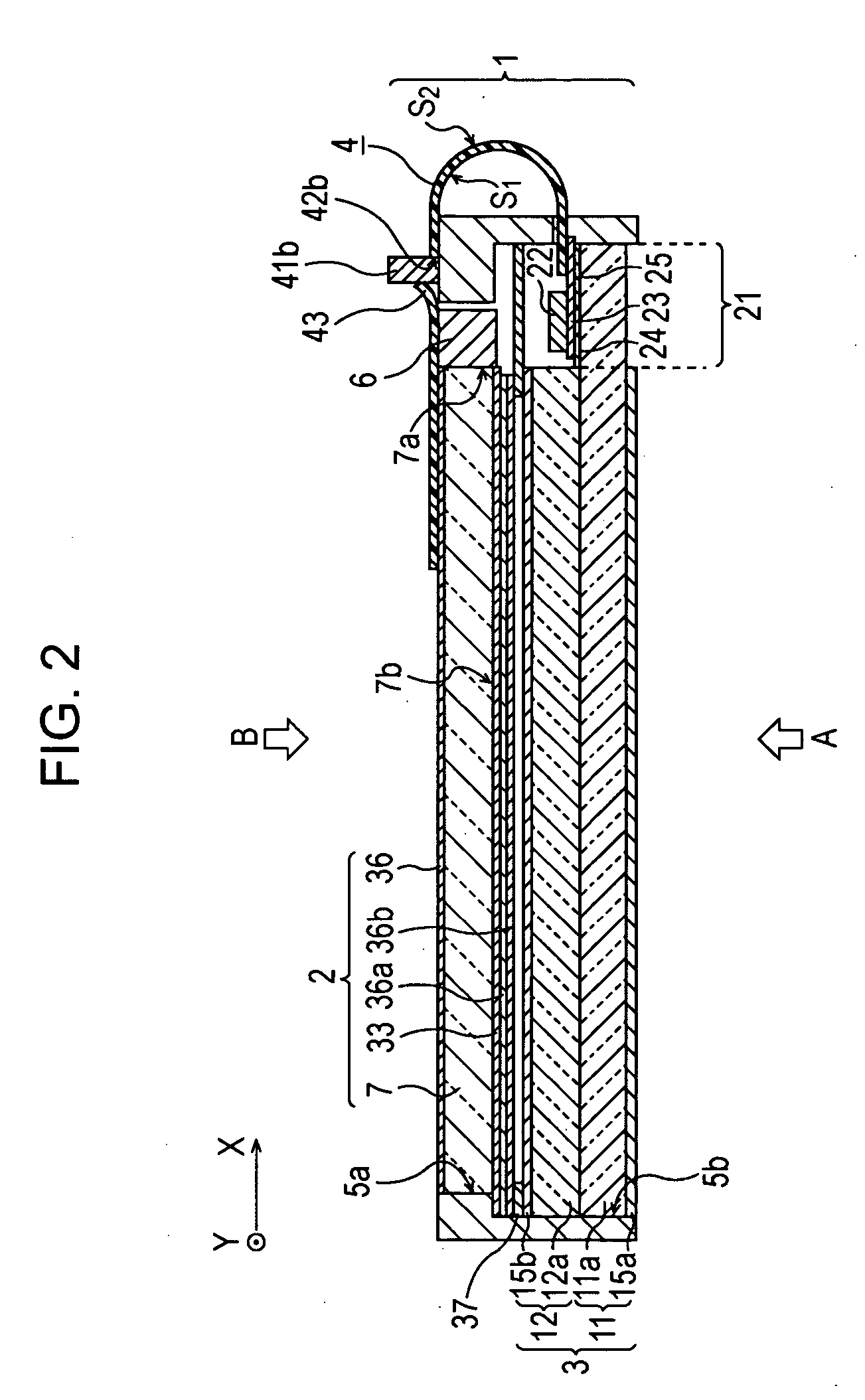
[0038]FIG. 1 illustrates the embodiment of the liquid crystal display device as the lighting device and electro-optical device using the lighting device in the disassembly state. In addition, FIG. 2 shows the cross section structure of the side part in assembling the liquid crystal display device in FIG. 1. The lighting device according to the embodiment, for example, is the lighting device with the configuration ...

second embodiment

the Lighting Device and Electro-Optical Device

[0077]FIG. 5 shows another embodiment according to the lighting device and the electro-optical device of the invention. Moreover, FIG. 6 shows the cross-sectional side structure when the liquid crystal display device of FIG. 5 is assembled. In the liquid crystal display device 1 corresponding to the previous embodiment shown in FIG. 1, there is employed the structure in which the LED 6 as a light source is mounted on the FPC board 4 connected with the liquid crystal panel 3. The liquid crystal display device 51 shown in FIG. 5 employs the structure that provides a LED board 58 in addition to the FPC board 54 connected to the liquid crystal panel 53 and mounts the LED 6 on the LED board 58.

[0078] Hereinafter, the liquid crystal display device 51 of FIG. 5 will be described from a different standpoint from the liquid crystal display device 1 of FIG. 1. In addition, the element as same as the embodiment of FIG. 1 is given the same symbol, ...

modified example

[0107] Besides the above-referenced cellular phone and so on, personal computers, liquid crystal televisions, viewfinder or monitor type of video tape recorders, car navigation devices, pagers, personal digital assistances, calculators, word processors, workstations, videophones, and point-of-sale terminals and the rest may be quoted as the electronic apparatus.


PUM


Abstract

A lighting device includes a board mounting a light source, a first hole provided in the board, a projecting part protruded inside the first hole from a periphery of the first hole, a light guide which receives a light emitted from the light source through a light receiving plane, and transmits the light from a light transmitting plane, and the first protrusion which is integrally formed in the light guide and is inserted into the first hole, wherein the projecting part presses a side of the first protrusion so that the board can move toward the light receiving plane.

Description

BACKGROUND [0001] 1. Technical Field [0002] The present invention relates to a lighting device transmitting a light emitted from a light source to a lighting section by using a light guide. In addition, it relates to an electro-optical device constituted by means of using the lighting device. Besides, it relates to an electronic apparatus constructed by using the electro-optical device. [0003] 2. Related Art [0004] Recently, an electro-optical device such as a liquid crystal display device is widely used for electronic apparatuses such as cellular phone, PDA, IC recorder and the like. For example, in order to display a variety of information about an electronic apparatus with an image, the electro-optical device is used. Since this electro-optical device performs the display by controlling a light through the electric control, a lighting device is required as a source of light. [0005] A lighting device used as an electro-optical device generally comprises a light guide formed by a t...

Claims


Application Information

Patent Timeline
IPC IPC(8): F21V7/04
CPCG02B6/0088G02B6/009H05B3/36H05B3/08H05B2203/013H05B2203/017
Inventor FUJIKAWA, YOICHIEDA, OSAMU
Owner BOE TECH GRP CO LTD
Why Eureka
Try Eureka