Lighting apparatus

Inactive Publication Date: 2013-03-07
CANON KK
View PDF7 Cites 19 Cited by
  • Summary
  • Abstract
  • Description
  • Claims
  • Application Information

AI Technical Summary

Benefits of technology

[0015]According to the present invention, it is possible to inhibit the generation of uninten

Problems solved by technology

Nevertheless, when the contrast of the image is improved by performing local dimming control to the backlight apparatus which realizes white light by using a plurality of colored light emitting devices (for instance, primary color light emitting diodes (LEDs)), unintended coloring is generated in the image.
For example, when the light source of one block is independently lit, it is difficult to mix the color of light from the primary color LED of the edge of that block since there are no LEDs of other colors emitting light outside the primary color LED.
In addition, since light from the foregoing primary color LED of the edge will

Method used


Image

  • Lighting apparatus
  • Lighting apparatus
  • Lighting apparatus

Examples


embodiment 1

[0024]Embodiment 1 of the present invention is now explained.

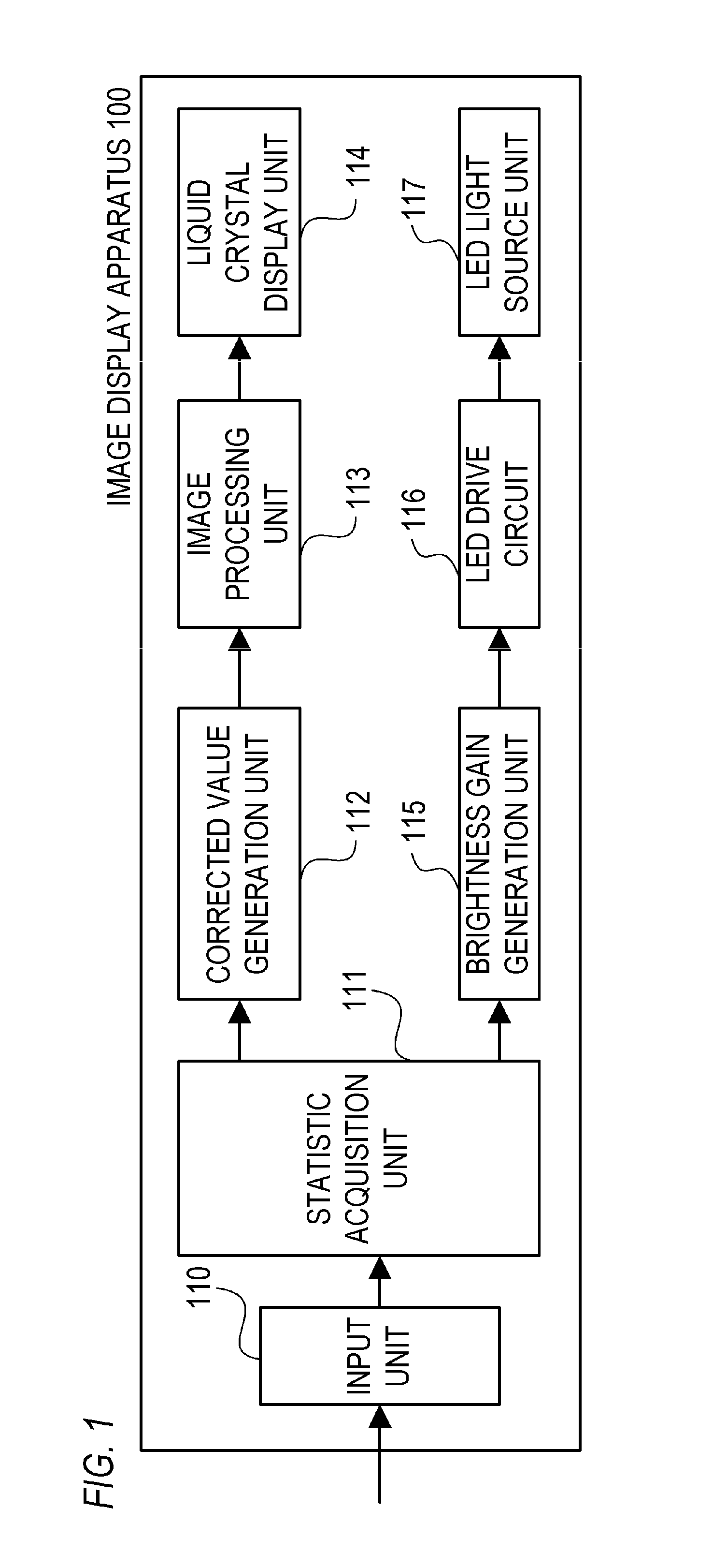
[0025]FIG. 1 is a block diagram showing an example of the functional configuration of an image display apparatus 100 (liquid crystal display apparatus) according to Embodiment 1. The image display apparatus 100 according to this embodiment is configured such that local dimming control can be performed. Specifically, the image display apparatus 100 performs, for each block (area) which is obtained by dividing the area of the screen into a plurality of areas, controlling of the brightness (light emitting brightness) or color (emission color) of the backlight apparatus (lighting apparatus), image processing, or the like.

[0026]The input unit 110 inputs an image signal from the outside, and transmits the input image signal to a statistic acquisition unit 111.

[0027]The statistic acquisition unit 111 acquires a statistic from the transmitted image signal. Specifically, the statistic acquisition unit 111 acquires, for each block, ...

embodiment 2

[0071]Embodiment 2 of the present invention is now explained.

[0072]Embodiment 2 explains a configuration of the backlight apparatus capable of yielding the effects explained in Embodiment 1 as well as achieving a thinner profile. Note that, since the basic configuration of the image display apparatus (liquid crystal display apparatus) is the same as Embodiment 1, the explanation thereof is omitted.

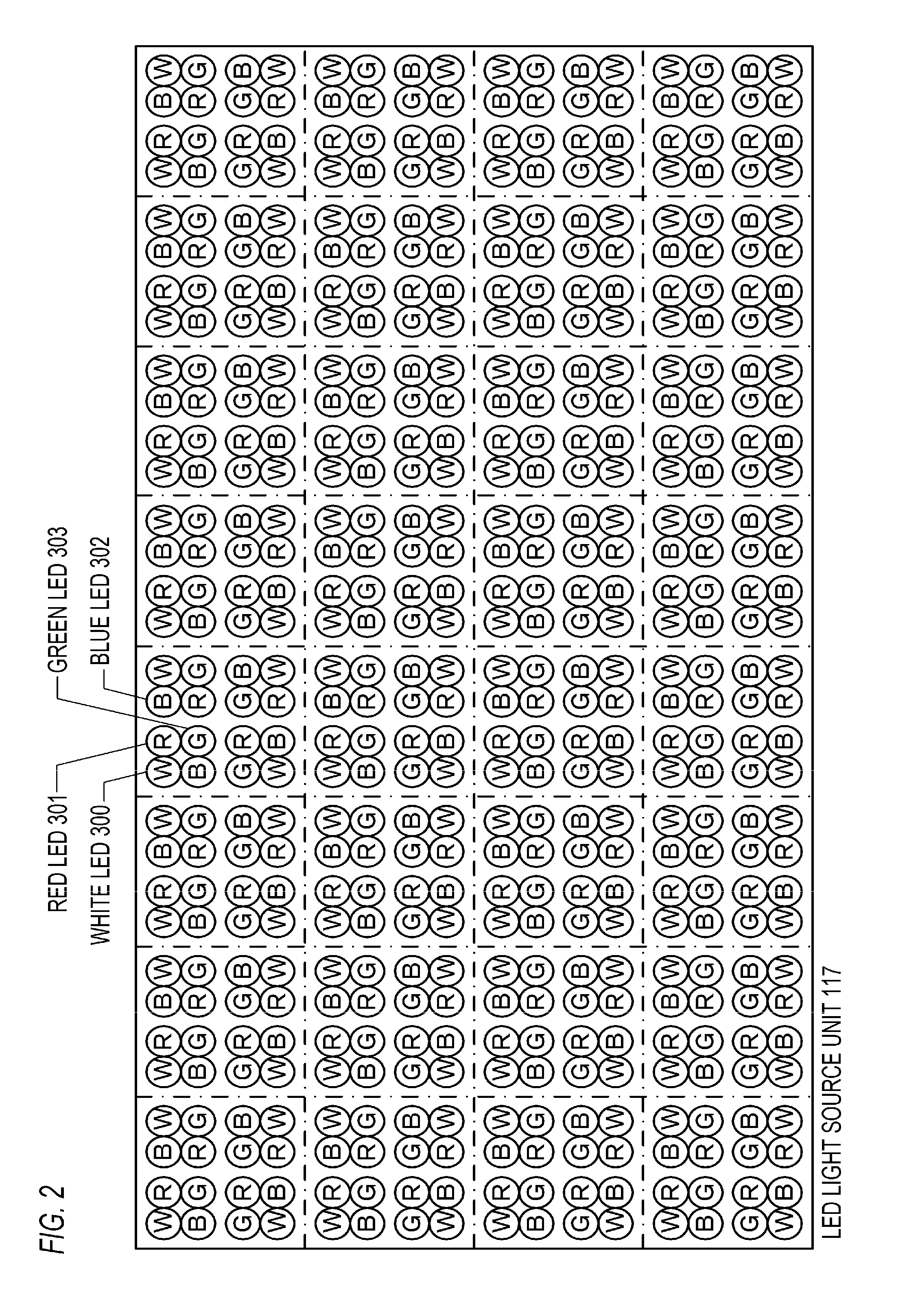
[0073]FIG. 5 is a diagram showing an example of the arrangement of the LEDs in the LED light source unit 350 (backlight apparatus) according to this embodiment.

[0074]In this embodiment, as shown in FIG. 5, the plurality of primary color LEDs of each block include a plurality of red LEDs, a plurality of green LEDs, and a plurality of blue LEDs. In addition, the plurality of LEDs of each block are arranged in a matrix so that the green LEDs are concentrated at the central portion.

[0075]Specifically, the green LED 303 of each group is disposed at the central portion side of the block.

[0076]Si...

embodiment 3

[0084]Embodiment 3 of the present invention is now explained.

[0085]This embodiment explains a configuration of the backlight apparatus in which the number of groups contained in one block is different from Embodiment 1. Note that, since the basic configuration of the image display apparatus (liquid crystal display apparatus) is the same as Embodiment 1, the explanation thereof is omitted.

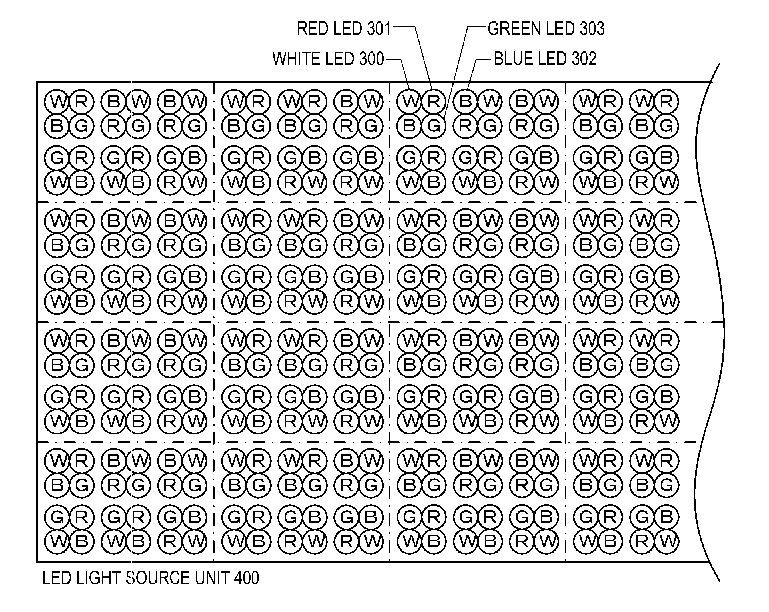
[0086]FIGS. 6A and 6B are diagrams showing an example of the arrangement of the LEDs in the LED light source units 400 and 410 (backlight apparatus) according to this embodiment.

[0087]FIGS. 6A and 6B are examples where six groups of the group shown in FIG. 1 are provided to one block. Specifically, FIG. 6A shows an example where the plurality of LEDs of each block are configured from six groups arranged in a 3×2 matrix. FIG. 6B shows an example where the plurality of LEDs of each block are configured from six groups arranged in a 2×3 matrix.

[0088]In the examples of FIGS. 6A and 6B also, as with Embo...


PUM


Abstract

A lighting apparatus according to the present invention is configured from a plurality of blocks controllable individually for brightness or color, wherein each of the blocks comprises a plurality of light emitting devices including a plurality of white light emitting devices and a plurality of colored light emitting devices, and the plurality of light emitting devices of each of the blocks are arranged in a matrix so that the white light emitting devices are positioned at four corners.

Description

BACKGROUND OF THE INVENTION[0001]1. Field of the Invention[0002]The present invention relates to a lighting apparatus.[0003]2. Description of the Related Art[0004]In recent years, a liquid crystal display (LCD) apparatus is known as a display apparatus of high definition, broad color gamut, and low power consumption.[0005]There are two methods for displaying the intended color temperature in a liquid crystal display apparatus. One method is to configure a backlight apparatus using a white light source (white light emitting device), and adjust the color temperature by image signal processing. The other method is to configure a backlight apparatus using a plurality of primary color lights sources (colored light emitting devices) such as red, green, and blue, and achieve additive color mixing by lighting the foregoing primary color light sources at a luminous intensity ratio that realizes the intended color temperature.[0006]Of the two methods described above, while the method of confi...

Claims


Application Information

Patent Timeline
IPC IPC(8): F21V9/00G02F1/13357G09G3/36G09F13/04
CPCG09G3/3413G09G3/3426G09G2320/0233G09G2370/22G09G2320/0646G09G2330/022G09G2360/16G09G2320/0242H05B45/44
Inventor MORISHITA, MASASHI
Owner CANON KK
Why Eureka
Try Eureka