

Color correction filter, image display, and liquid crystal display
- Summary
- Abstract
- Description
- Claims
- Application Information
AI Technical Summary
Benefits of technology
Problems solved by technology
Method used
Image

Examples
example 1
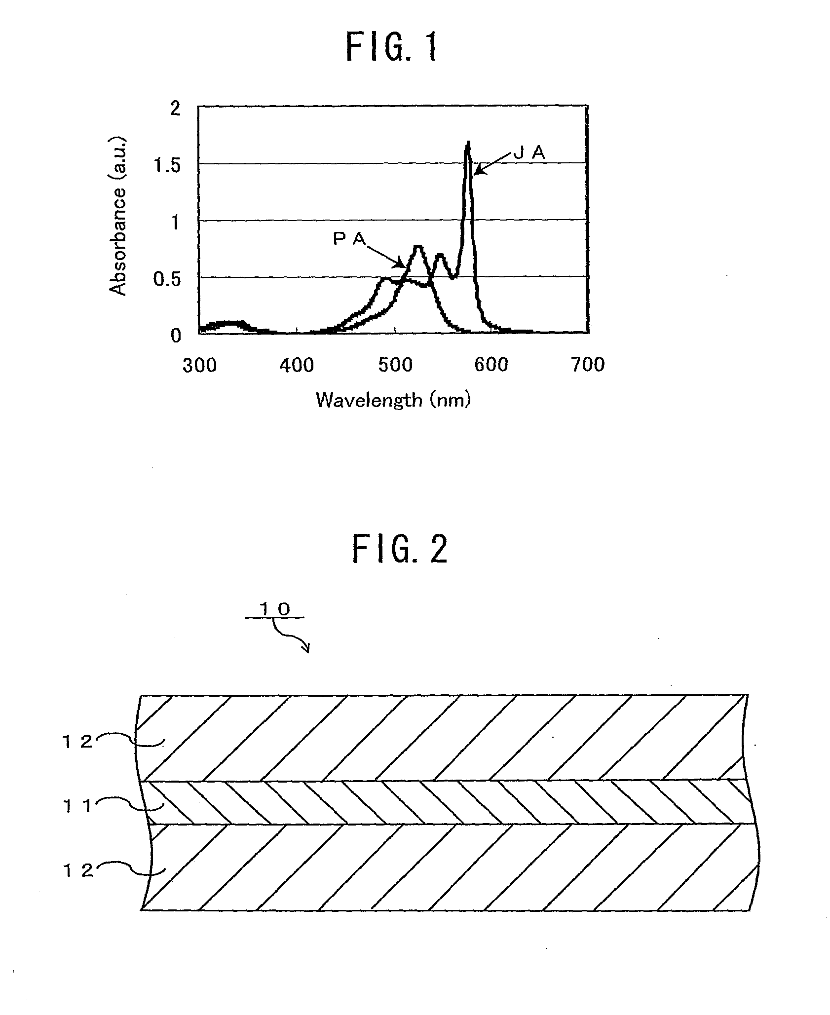
[0077]A color correction filter with a structure shown in FIG. 2 was produced.
[0078]That is, first, a dye (1-ethyl-2-[(1-ethyl-2(1H) -quinolinylidene)methyl]quinolinium bromide (manufactured by Hayashibara Biochemical Labs., Inc.), Br− salt of an ion represented by the aforementioned structural formula (5), was dissolved in ethanol and thereby 1.2 g / L of coating solution for a color correction layer was obtained.
[0079]Next, with the coating solution being allowed to drip onto a first protective layer (glass sheet), the coating solution was applied by the spin coating method under a condition of 1000 times / min×30 sec, and thereby a coating film was formed and was then dried. Thus, a color correction layer containing a J aggregate of the dye was formed on the first protective layer. The wavelength of the maximum absorption peak of the color correction layer was 577 nm, the half bandwidth at the maximum absorption peak was 10 nm, and the absorbance at the wavelength of the maximum abso...
example 2
[0082]A color correction filter of this example was obtained in the same manner as in Example 1 except that an ethylene-vinylalcohol copolymer film (with a thickness of 30 μm, “SOARNOL® 29” (trade name), manufactured by The Nippon Synthetic Chemical Industry Co., Ltd.) having a moisture barrier function and an oxygen barrier function was used as the second protective layer.
example 3
[0083]A color correction filter having a structure shown in FIG. 2 was produced.
[0084]That is, first, a dye that was identical to that used in Example 1 was used, and PVA (manufactured by The Nippon Synthetic Chemical Industry Co., Ltd., with a polymerization degree of 1800 and a saponification degree of 98.0 to 99.0 mol %) was used as the matrix resin. The dye, PVA, and zinc chloride (crosslinker) were dissolved in water at a weight ratio of dye:PVA:zinc chloride=10:56:34, and thereby a coating solution for the color correction layer was obtained in which the dye concentration was 1.1 g / L.
[0085]Next, with the coating solution being allowed to drip onto a first protective layer (glass sheet), the coating solution was applied by the spin coating method under a condition of 1000 times / min×30 sec, and thereby a coating film was formed. It was then dried and PVA was crosslinked. In this color correction layer, the wavelength of the maximum absorption peak was 574 nm, the half bandwidth ...
PUM
 Abstract
Description
Claims
Application Information