Viewing angle control element and image display based on same

a control element and angle technology, applied in the direction of polarising elements, identification means, instruments, etc., can solve the problems of image darkness and difficult recognition, and achieve the effect of preventing the degrading of image quality by falling brightness of the image display elemen

Active Publication Date: 2009-06-23
SHARP KK
View PDF16 Cites 18 Cited by
  • Summary
  • Abstract
  • Description
  • Claims
  • Application Information

AI Technical Summary

Benefits of technology

[0030]The present invention has an objective to provide a viewing angle control element which achieves both wide and narrow viewing angles while preventing the falling brightness of the image display element from degrading the image quality in the wide viewing angle. Another objective is to provide an image display based on the element.

Problems solved by technology

Even if the image is visible, the image appears dark and difficult to recognize.

Method used


Image

  • Viewing angle control element and image display based on same
  • Viewing angle control element and image display based on same
  • Viewing angle control element and image display based on same

Examples


embodiment 2

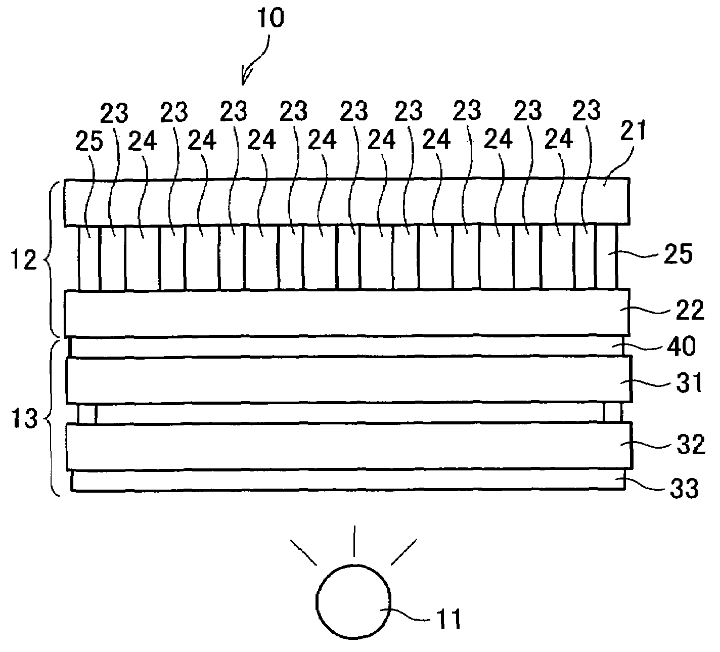
[0112]Next, referring to FIG. 4 and FIG. 5, principles in producing displays on the image display of the present embodiment will be described. In the present embodiment, the light shield regions 24 are formed of a polymer-dispersed liquid crystal.

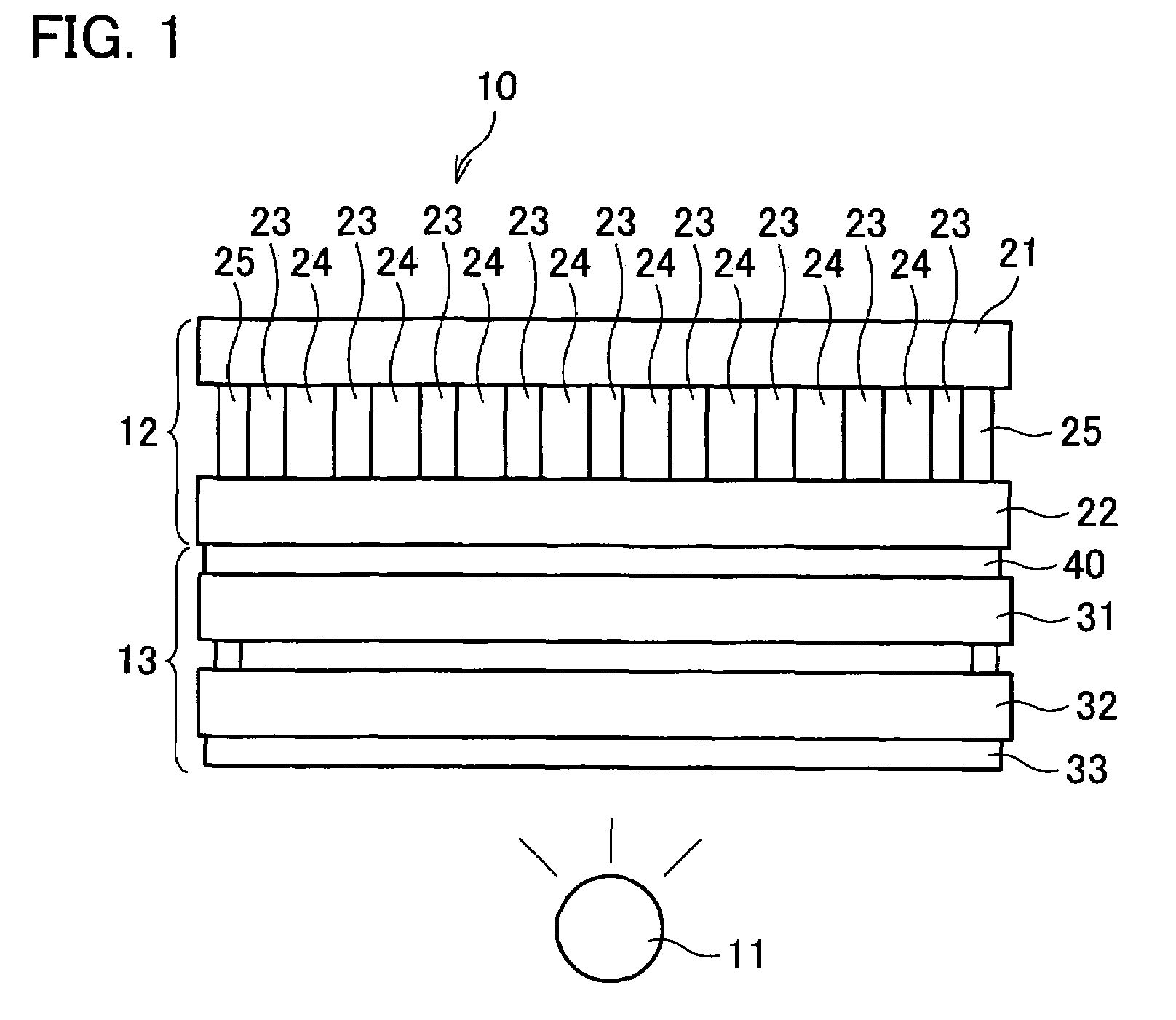
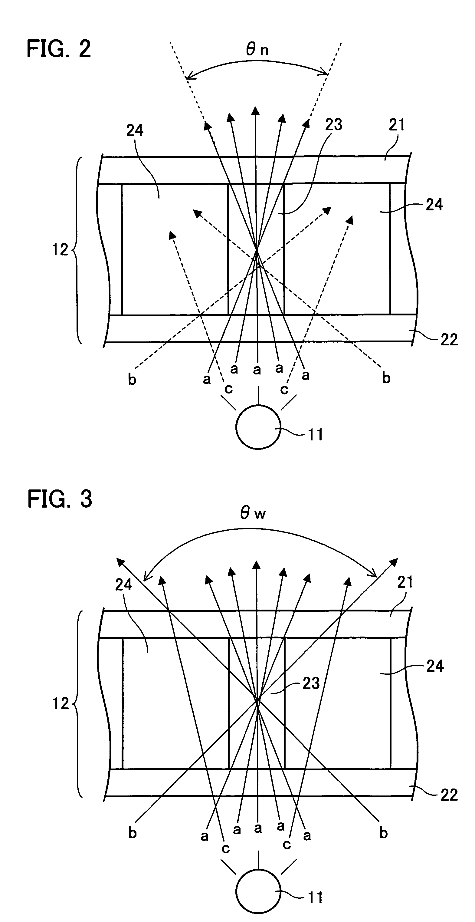
[0113]FIG. 4 is an enlarged cross-sectional view of the image display of the present embodiment, illustrating principles in producing displays in narrow viewing angle mode. Display principles will be described in reference to FIG. 4.

[0114]Light, upon entering the viewing angle control element 12, is diffused, but not polarized. Of the light beams incident to the transparent region 23 which is a pillared transparent resin layer in the viewing angle control element 12, beams (a) within the angle θn (see the figure) leave the viewing angle control element 12, unaffected by the polymer-dispersed liquid crystal provided in the light shield region 24.

[0115]Meanwhile, relatively highly diffused beams (b) outside the angle θn (see the figure) pass ...

examples

[0130]To illustrate the viewing angle control element 12 of the present invention more specifically, examples of the present invention will be now given. The viewing angle control elements 12 in the examples were fabricated by the following steps. First, a laminator of a negative resist for a thick film (product name: “ASF series” available from Hitachi Chemical Co., Ltd.) was transferred on to the glass substrate 2 provided with ITO (not shown) by high temperature substrate overheat. The laminator was exposed using a photo mask to form a desired pattern of a pillared transparent resin layer for the viewing angle control element 12. Under these circumstances, the laminator was exposed to ultraviolet rays (quantity: 200 mJ), developed for 1 minute in an 2% aqueous solution of NaOH at 30° C., washed, and baked for 40 minutes at 230° C. in a clean oven, to form a stripe pattern of the pillared transparent resin layer measuring 40 μm in thickness and 12 μm in width.

[0131]Next, an alignm...


PUM

PropertyMeasurementUnit
thicknessaaaaaaaaaa
thicknessaaaaaaaaaa
transparentaaaaaaaaaa

Abstract

A viewing angle control element of the present invention contains transparent regions 23 having a transmittance T1 and light shield regions 24 capable of switching between a transmittance T2 and a transmittance T3 which is less than T1 and T2 according to an external signal. Each of the transparent regions 23 and the light shield regions 24 is positioned opposite to one of pixels. Displays are produced at or close to the original brightness of the image display element in wide viewing angle mode, whereas in narrow viewing angle mode, light transmission is limited to achieve narrow viewing angles. This is in contrast with other viewing angle control elements which produce displays at or close to the original brightness of the image display element in narrow viewing angle mode, whereas in wide viewing angle mode, light is diffused or otherwise modified to achieve wide viewing angles. Thus, the viewing angle control element is capable of achieving both wide viewing angles and narrow viewing angles, and still preventing image quality deterioration at wide viewing angles due to decreased brightness of the image display element.

Description

[0001]This Nonprovisional application claims priority under 35 U.S.C. § 119(a) on Patent Application No. 2004-029428 filed in Japan on Feb. 5, 2004, the entire contents of which are hereby incorporated by reference.FIELD OF THE INVENTION[0002]The present invention relates to viewing angle control elements switching an image display between wide viewing angle mode and narrow viewing angle mode. The invention also relates to image displays, based on the element, the viewing angles of which are controllable.BACKGROUND OF THE INVENTION[0003]Liquid crystal displays have been enjoying great popularity. Taking advantage of their features-slimness, low weight, and low power consumption, they are achieving rapidly growing use in various fields, not to mention mobile applications.[0004]Mobile phone applications are especially notable. The slimness, low weight, and low power consumption features have been enhanced. On top of that, the liquid crystal display now boasts excellent visibility owin...

Claims


Application Information

Patent Timeline
Patent Type & Authority Patents(United States)
IPC IPC(8): G02F1/1335G02B27/00G02B5/30G02F1/13G02F1/133G02F1/1333G02F1/1334G02F1/1347G09F9/00
CPCG02F1/1323G02F1/1347G02F1/13475G02F1/13476A47J37/0676A47J37/0781A47J37/0786
Inventor FUKUSHIMA, HIROSHIYABUTA, KOJITAKATANI, TOMOOWADA, MASAKAZU
Owner SHARP KK
Why Eureka
Try Eureka