User configurable stackable display

a stackable display and user-configurable technology, applied in the field of stackable display shelves, can solve the problems of high manufacturing cost, over-complexity, and disadvantages of prior art constructions

Inactive Publication Date: 2006-09-21
CHEN JACK
View PDF6 Cites 47 Cited by
  • Summary
  • Abstract
  • Description
  • Claims
  • Application Information

AI Technical Summary

Benefits of technology

[0005] Provided is a user-configurable display which can be both vertically and horizontally arranged to achieve any desired arrangement. In one aspect, the invention provides a display that has shelves that can be variable in length with shelf ends that fit within corner pieces. The corner pieces can be curve-shaped, T-shaped, and cross-shaped. A locking mechanism such as a cam engages each shelf end such that the shelves are engaged to the corner pieces. A cover piece covers the corner pieces and hides the locking mechanism from view. Each shelf end includes a raised section that fits within lips of the corner pieces and one or more bores for receiving a cam bolt that engages the cams.

Problems solved by technology

Although the known constructions have attempted to provide a connection between the shelf members and the upright support members which is durable, less susceptible to wear, and more stable, such prior art constructions still suffer from certain disadvantages and shortcomings.
For example, all of the features associated with the known prior art constructions have made such units overly complex, expensive to manufacture, require a large number of parts and / or components to assemble which is both inconvenient and time consuming.
Additionally, known prior art is limited in that the display shelves are fixed in length and / or width.

Method used


Image

  • User configurable stackable display
  • User configurable stackable display
  • User configurable stackable display

Examples


Embodiment Construction

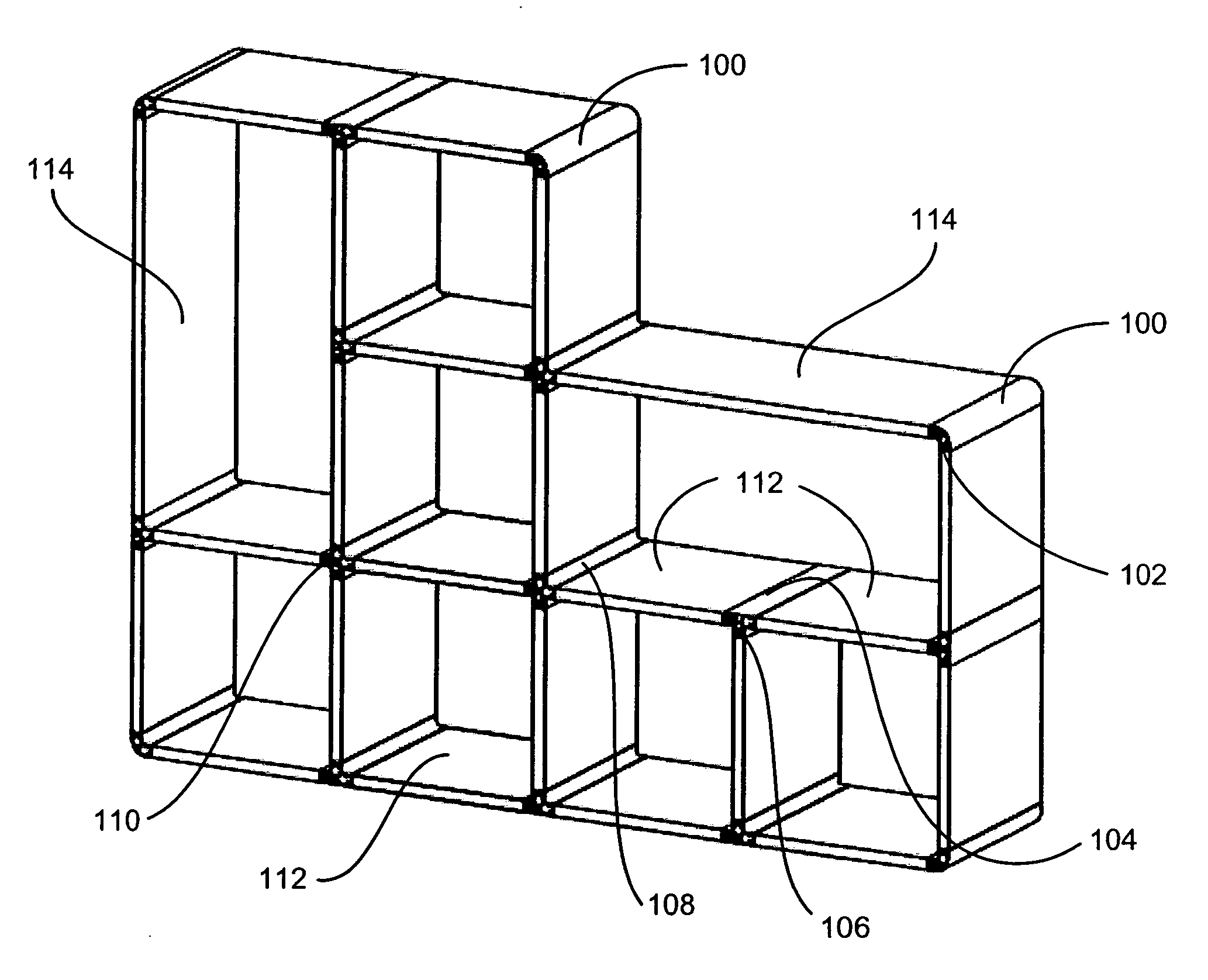
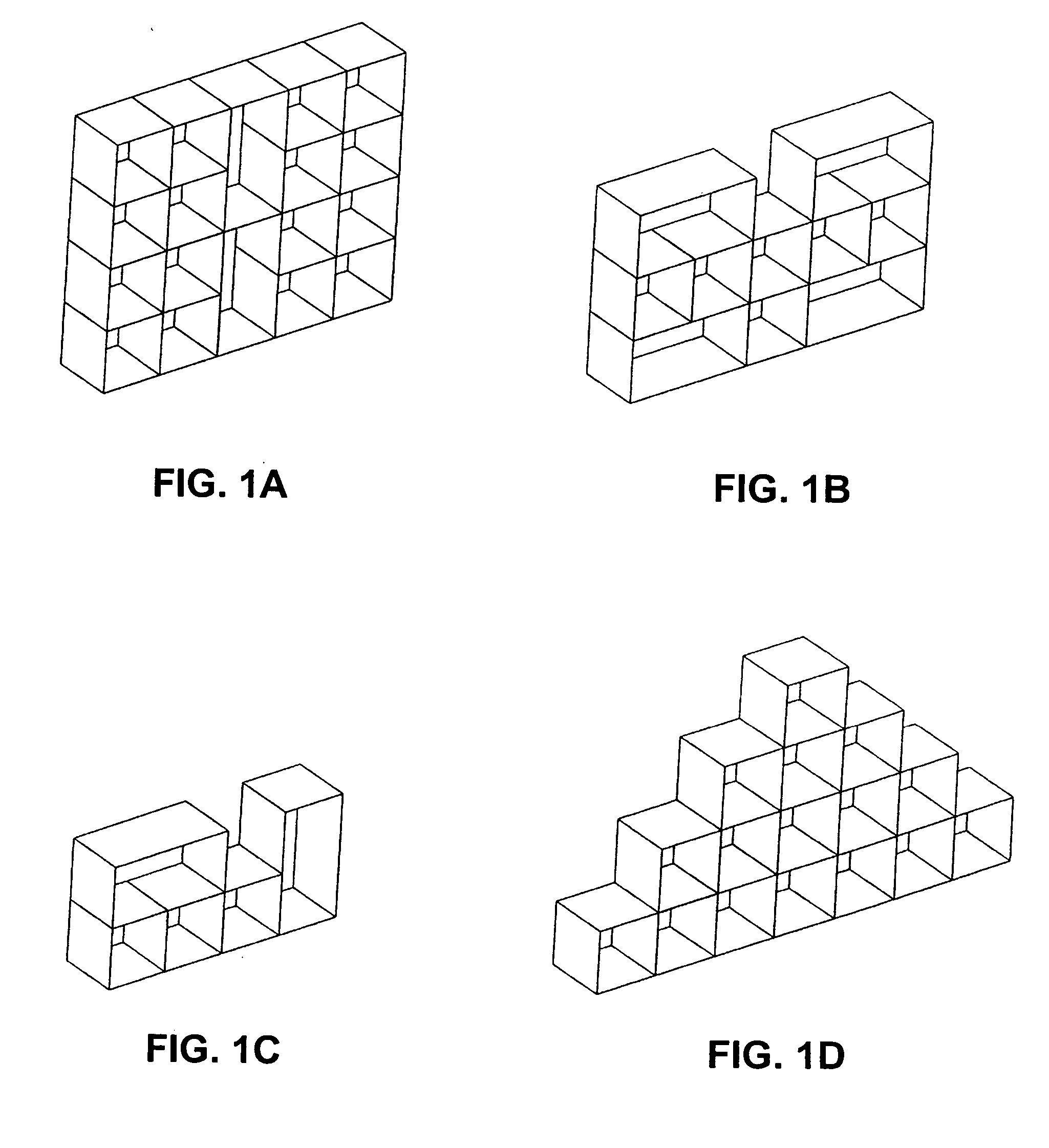
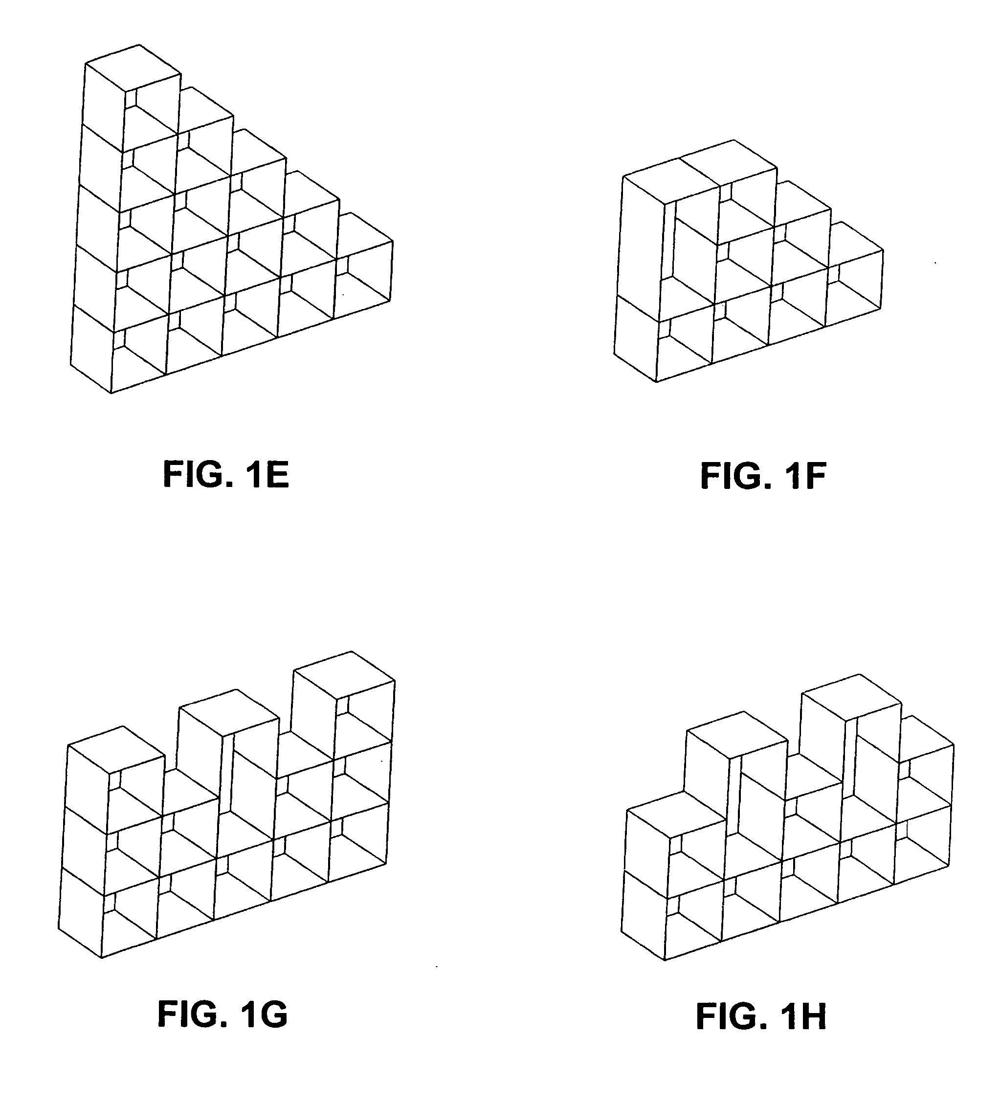
[0029] Turning to the drawings, wherein like reference numerals refer to like elements, the user-configurable stackable display can be configured in a variety of heights, widths, and lengths. For example, FIGS. 1(a)-1(k) provide an example of the different shapes that can be made using various corner pieces 100, 104, 108 with end pieces 102, 106, 110 and various shelf pieces 112, 114. While two shelf pieces 110, 112 are shown, the shelf pieces can be configured to be any length. In the description that follows, shelf pieces 112, 114 shall be used to describe the user-configurable display shelf. The corner pieces 100, 104, 108 may be made of various materials, including plastic, aluminum, steel, etc. The shelf pieces 112, 114 can be of any material, including wood, plastic, metal, glass, fiberboard such as MDF (medium density fiberboard) with a wood skin, and the like.

[0030] The end pieces 102, 106, 112 are typically made of the same material as a corner piece, but could be made fro...


PUM

PropertyMeasurementUnit
lengthaaaaaaaaaa
durableaaaaaaaaaa
widthaaaaaaaaaa

Abstract

A user-configurable display is provided. The display has shelves that can be variable in length with shelf ends that fit within corner pieces. The corner pieces can be arcuate-shaped, T-shaped, and cross-shaped. A locking mechanism such as a cam engages each shelf end such that the shelves are engaged to the corner pieces. A cover piece covers the corner pieces and hides the locking mechanism from view. Each shelf end will fit into the lips of the corner pieces and has one or more bores for receiving a cam bolt that engages the cams. A shelf end may include a raised section that fits within the lips of the corner pieces.

Description

CROSS-REFERENCE TO RELATED PATENT APPLICATIONS [0001] This patent application claims the benefit of U.S. Provisional Patent Application No. 60 / 663,343, filed Mar. 18, 2005, the teachings and disclosure of which are hereby incorporated in their entireties by reference thereto.FIELD OF THE INVENTION [0002] This invention generally relates to displays, and more generally to stackable display shelves. BACKGROUND [0003] Office and home users use display shelves for a variety of purposes. A wide variety of such products are available, including shelves, racks, baskets, and like arrangements, which facilitate convenient storage of articles where desired. Displays for storing and merchandising a multiplicity of products having shelves which are vertically stackably arranged in spaced relationship one above the other are known. Although the known constructions have attempted to provide a connection between the shelf members and the upright support members which is durable, less susceptible t...

Claims


Application Information

Patent Timeline
Patent Type & Authority Applications(United States)
IPC IPC(8): A47B47/00
CPCA47B47/0025A47B47/0066A47B47/0091
Inventor CHEN, JACK
Owner CHEN JACK
Why Eureka
Try Eureka