Fuel cut off valve

a technology of fuel cut off valve and fuel tank, which is applied in the direction of functional valve types, liquid fuel feeders, machines/engines, etc., can solve the problem of incompatibility with the demands of flattening fuel tanks

Active Publication Date: 2006-09-28
TOYODA GOSEI CO LTD
View PDF9 Cites 37 Cited by
  • Summary
  • Abstract
  • Description
  • Claims
  • Application Information

AI Technical Summary

Benefits of technology

[0020] Moreover, another form of embodiment according to the present invention is provided with fuel cut off valve that is to be attached to an upper portion of a fuel tank and opens and closes a connection conduit for connecting an inside of the tank to outside of the tank according to a fuel level in the fuel tank, the cut off valve comprising a casing including (i) a first valve chamber that is connected to the inside of the fuel tank, (ii) a second valve chamber that is connected to the first valve chamber, (iii) a first connection conduit that connects the first valve chamber and the second valve chamber, (iv) a first seal part that is formed on an opening peripheral part of the first connection conduit, (v) a second connection conduit that connects the second valve chamber and the outside, and (vi) a second seal part that is formed on an opening peripheral part of the second connection conduit. The fuel cut off valve further comprises a first valve mechanism, housed in the first valve chamber, that seats on the first seal part to close the first connection conduit when the fuel level reaches a first liquid level; a second valve mechanism, housed within the second valve chamber and seats on the second seal part to close the second connection conduit when the fuel level reaches a second liquid level, the second liquid level being higher than the first liquid level; and a restriction path, formed between the first valve chamber and the second valve chamber, that forms a path area that is smaller than the conduit area of the first connection conduit, so as to cause the pressure within the fuel tank to rise when the first valve mechanism seats on the first seal part.

Problems solved by technology

While in recent years there have been demands for flattening the fuel cut off valves, accompanying flattened fuel tanks, the conventional valve requires a middle chamber between the upper chamber and the bottom chamber and thus the shape of the fuel cut off valve is large in the vertical direction, making it incompatible with the demands for flattened fuel tanks.
However, even in this other conventional valve, the upper chamber is disposed above each of the lower chambers, and thus there is the same problem as the valve descried above.

Method used


Image

  • Fuel cut off valve
  • Fuel cut off valve
  • Fuel cut off valve

Examples


first embodiment

A. First Embodiment

[0037] (1) Schematic Structure of the Fuel Cut off Valve

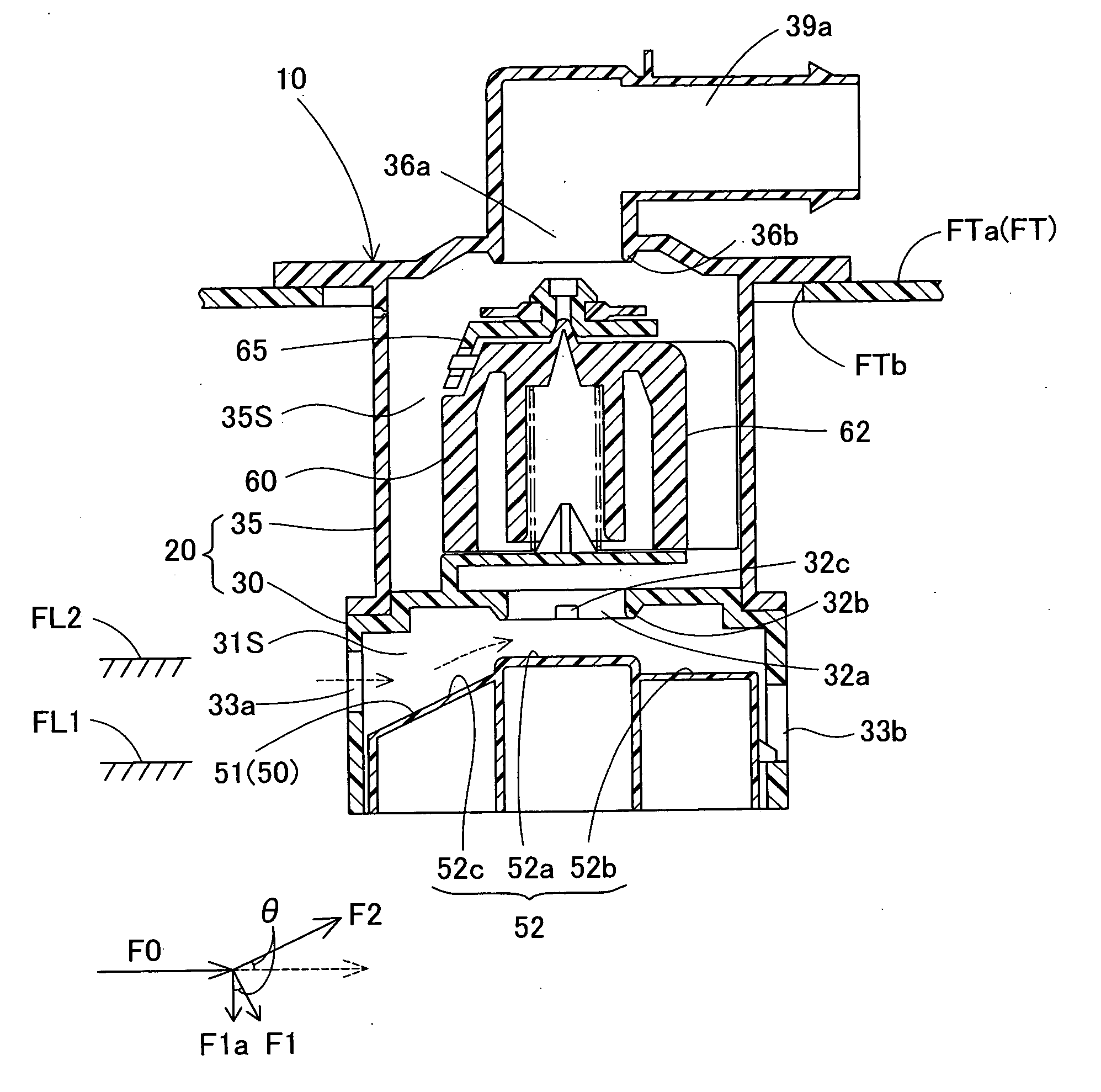
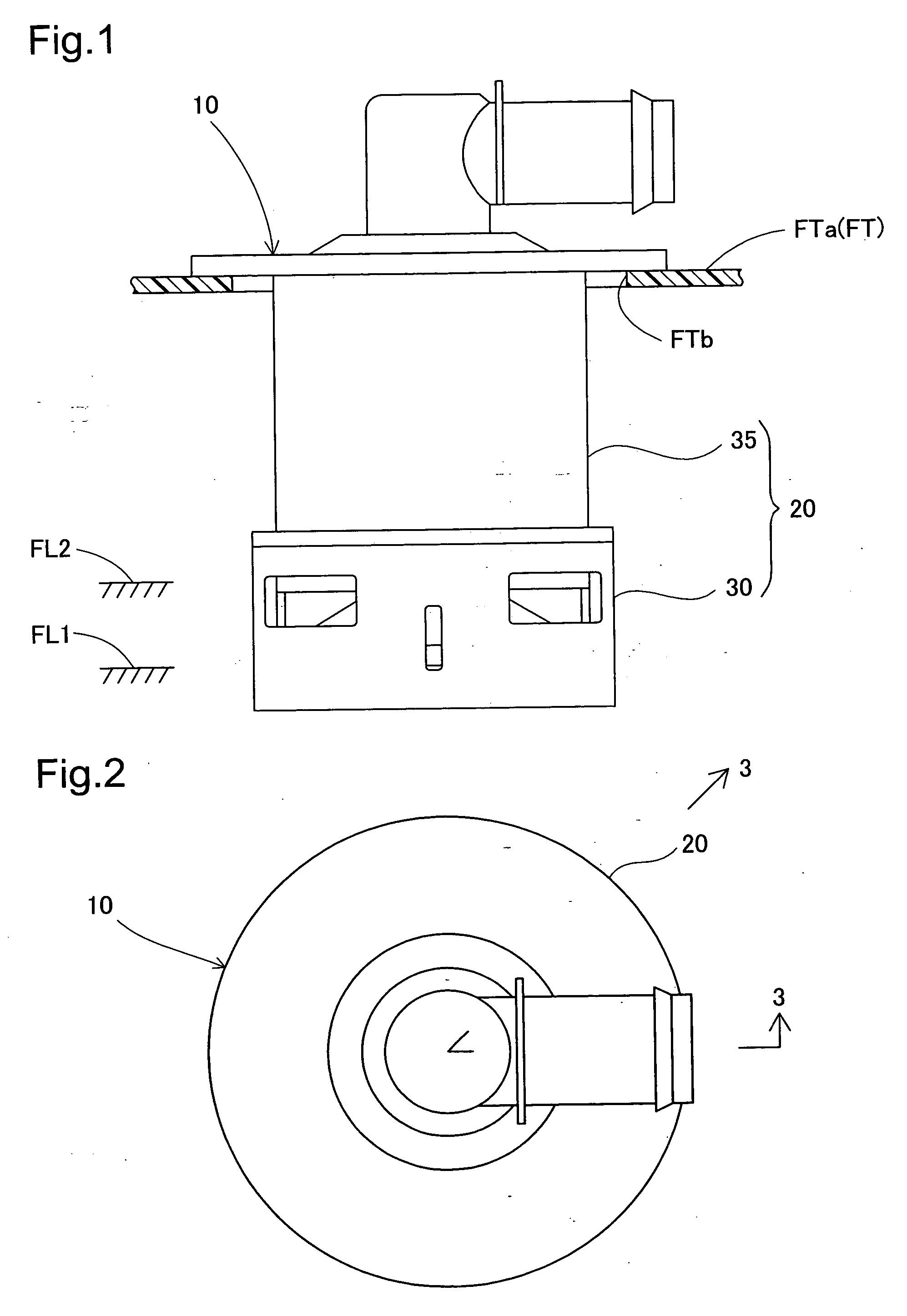
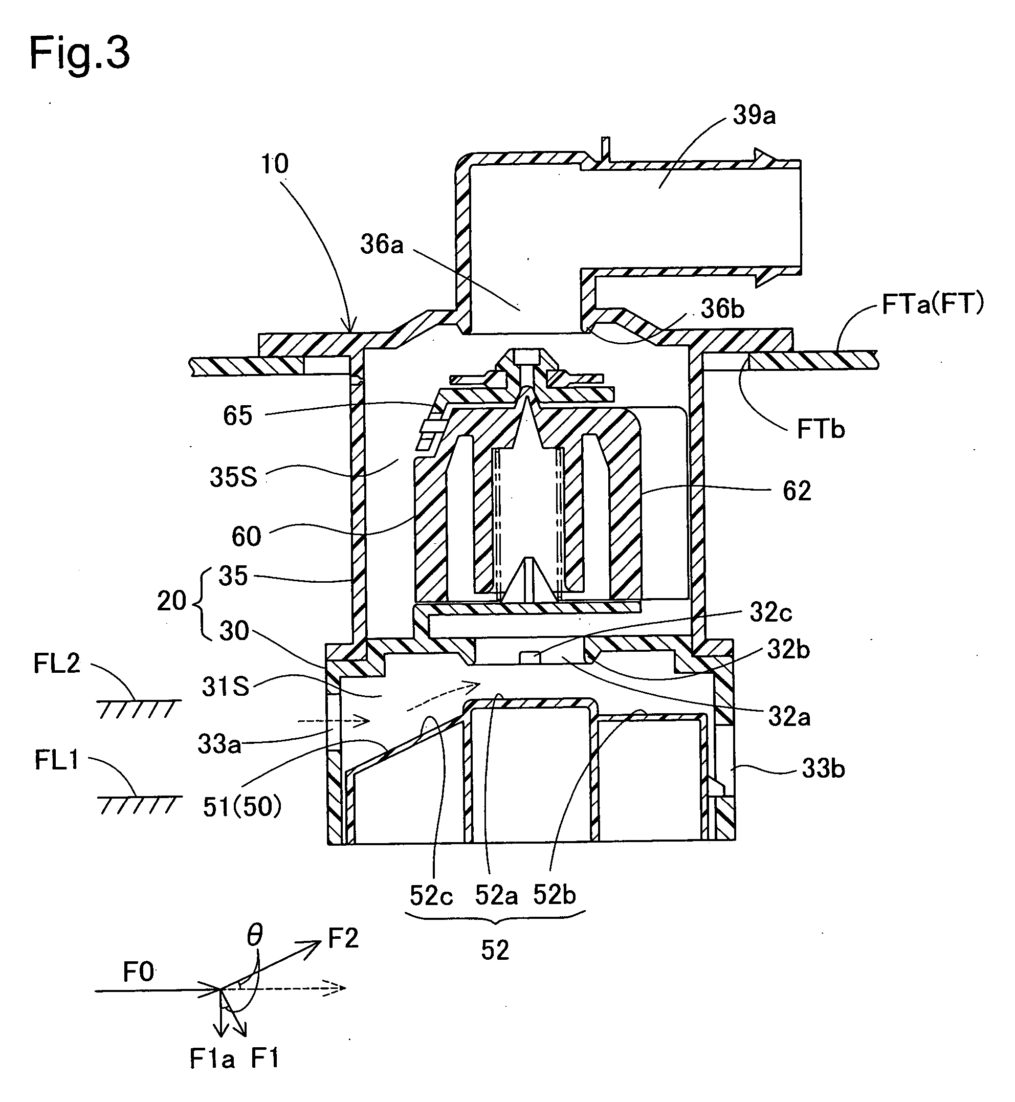
[0038]FIG. 1 is a side view showing a fuel cut off valve 10 attached to the upper wall of a fuel tank FT of a vehicle, according to a first embodiment of the present invention, FIG. 2 is a plan view of the fuel cut off valve 10, and FIG. 3 is a cross-sectional view along 3-3 line of FIG. 2. In FIG. 1, the fuel tank FT is fabricated from a compound resin material including polyethylene in the surface layer thereof, where at an attachment hole FTb are formed in a tank upper wall FTa. The fuel cut off valve 10 is attached on the tank upper wall FTa with the lower part thereof inserted into the attachment hole FTb. The fuel cut off valve 10 controls the flow of fuel within the fuel tank from flowing out to the canister when, during fueling, the fuel reaches a first liquid level FL1, and also triggers the auto-stop function, and prevents overfilling when the second liquid level FL2 is exceeded.

[0039] (2) Structu...

second embodiment

B. Second Embodiment

[0064]FIG. 11 is a cross-sectional view showing a fuel cut off valve 10B according to a second embodiment. The second embodiment has, as its distinctive feature, a valve conduit 32Bc. In other words, a valve conduit 32Bc is formed in the top wall 32B (partition wall) that divides between the first valve chamber 31BS and the second valve chamber 35BS. Moreover, the structure of the first casing part 30B and the structure of the first valve mechanism 50B is somewhat different from the structure in the first embodiment. The lower opening 31Ba of the first casing part 30B is covered by a bottom cover 31B, and a connection hole 31Bb is formed in the bottom cover 31B.

[0065] In this structure, not only does the fuel block the connection hole 31Bb of the bottom cover 31B when the fuel level reaches the first liquid level FL1, but also the fuel is caused to flow into the first valve chamber 31BS by the differential pressure between the first valve chamber 31BS and the fu...

third embodiment

C. Third Embodiment

[0066]FIG. 12 is a cross-sectional view illustrating a fuel cut off valve 10C according to a third embodiment. The third embodiment has a structure that is different from that of the second embodiment, with a first casing part 30C and a second casing part 35C of the casing 20C disposed in parallel and not only connected by an valve conduit 32Cc, but wherein a first valve mechanism 50C and a second valve mechanism 60C are housed within the first and second casing parts 30C and 35C. While the structure and opening / closing action in the third embodiment are essentially the same as those in the second embodiment, a drain mechanism 80 for draining the fuel that accumulates in the second valve chamber 35Cs is provided. The drain mechanism 80 is provided with a valve body 81 that passes through a drain conduit 35CPa, which passes through the bottom cover 35CP. The valve body 81 comprises a catching part 81a that mates with the bottom cover 35CP, and a buoyancy part 81b t...


PUM


Abstract

A fuel valve comprises a first valve chamber and a second valve chamber within a casing, where a first valve mechanism and a second valve mechanism are housed in the respective valve chambers. A first float of the first valve mechanism rises when the fuel level reaches a first liquid level, to close a first connection conduit. The second valve mechanism rises to close a second connection conduit when a second liquid level, which is higher than the first liquid level is reached. A valve conduit, which acts as a restriction path, is provided between the first valve chamber and the second valve chamber. The valve conduit is formed with a conduit area that is less than that of the first connection conduit, so as to increase the pressure within the fuel tank when the first connection conduit is closed.

Description

[0001] This application claims the benefit of and priority from Japanese Application No. 2005-81476 filed Mar. 22, 2005, the content of which is incorporated herein by reference. BACKGROUND OF THE INVENTION [0002] 1. Field of the Invention [0003] The present invention relates to a fuel cut off valve mounted on an upper wall of a fuel tank to open and close a connection conduit, which connects the inside of the fuel tank with the outside. [0004] 2. Description of the Related Art [0005] A well known fuel cut off valve is described in JP-A-7-293,384 and U.S. Pat. No. 5,535,772. The valve comprises two-stage tank fill control valve that has the function of preventing overfill and blowback from filling ports. The valve comprises a bottom valve chamber, a middle valve chamber, and an upper valve chamber, which are disposed from the bottom to the upper portion within a casing, a lower float that is housed within the bottom valve chamber and an upper float that is housed within the upper va...

Claims


Application Information

Patent Timeline
Patent Type & Authority Applications(United States)
IPC IPC(8): F16K24/04
CPCF16K24/044Y10T137/3099
Inventor MIURA, NATSUSHIAOKI, TOMOHIDE
Owner TOYODA GOSEI CO LTD
Why Eureka
Try Eureka