

Vibration isolating bushing with embedded angular position sensor
- Summary
- Abstract
- Description
- Claims
- Application Information
AI Technical Summary
Benefits of technology
Problems solved by technology
Method used
Image

Examples
Embodiment Construction
[0043] The present invention is intended for application in automotive vehicle suspension systems and will be described in that context. It is to be understood, however, that the present invention could also be successfully applied in many other applications. Accordingly, the claims herein should not be deemed as limited to the specifics of the preferred application as described hereunder.
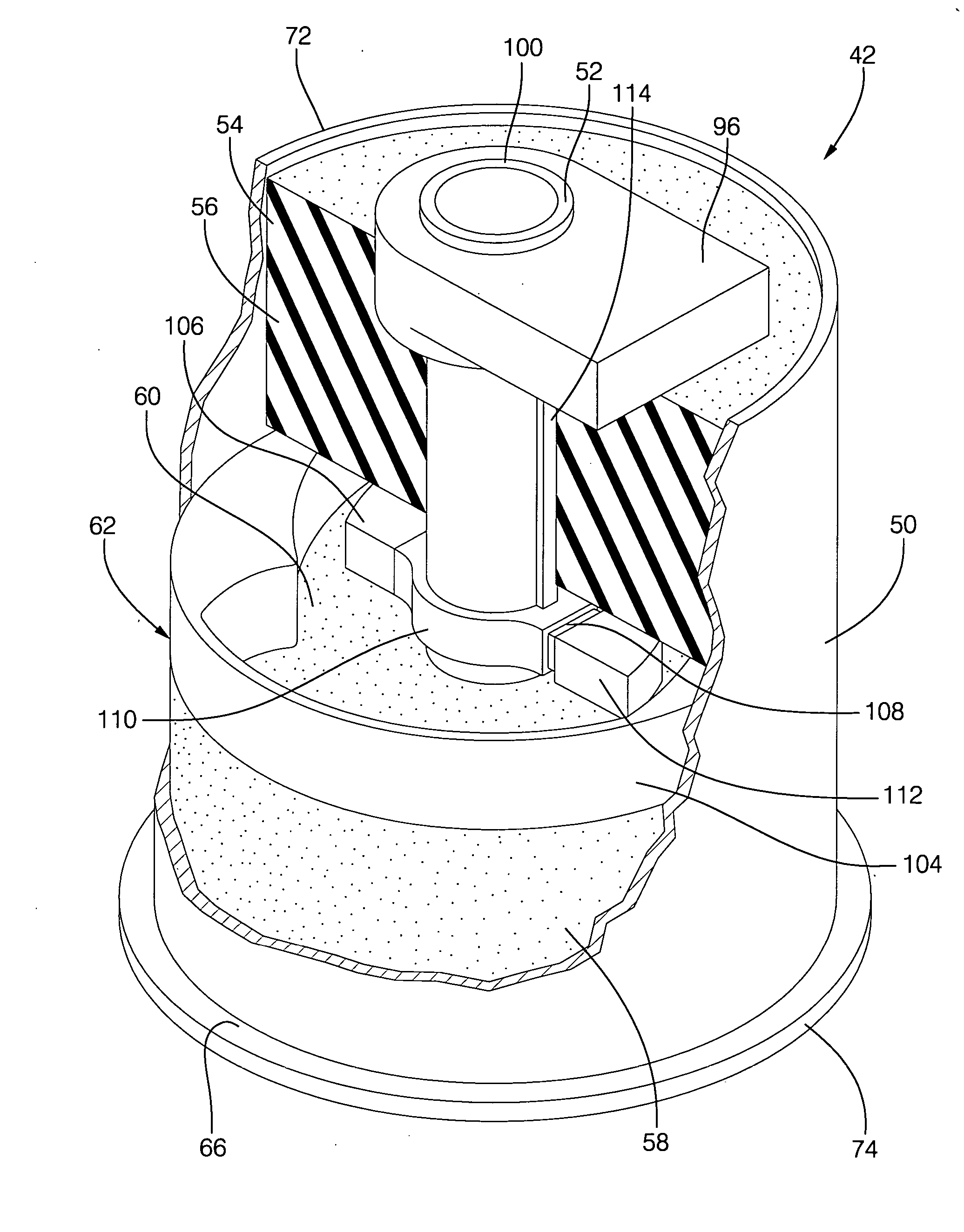
[0044] The preferred embodiment of the present invention serves as both a bushing for mounting suspension system components to an automotive vehicle as well as a sensor to monitor the position of selected suspension components while the vehicle is in operation.
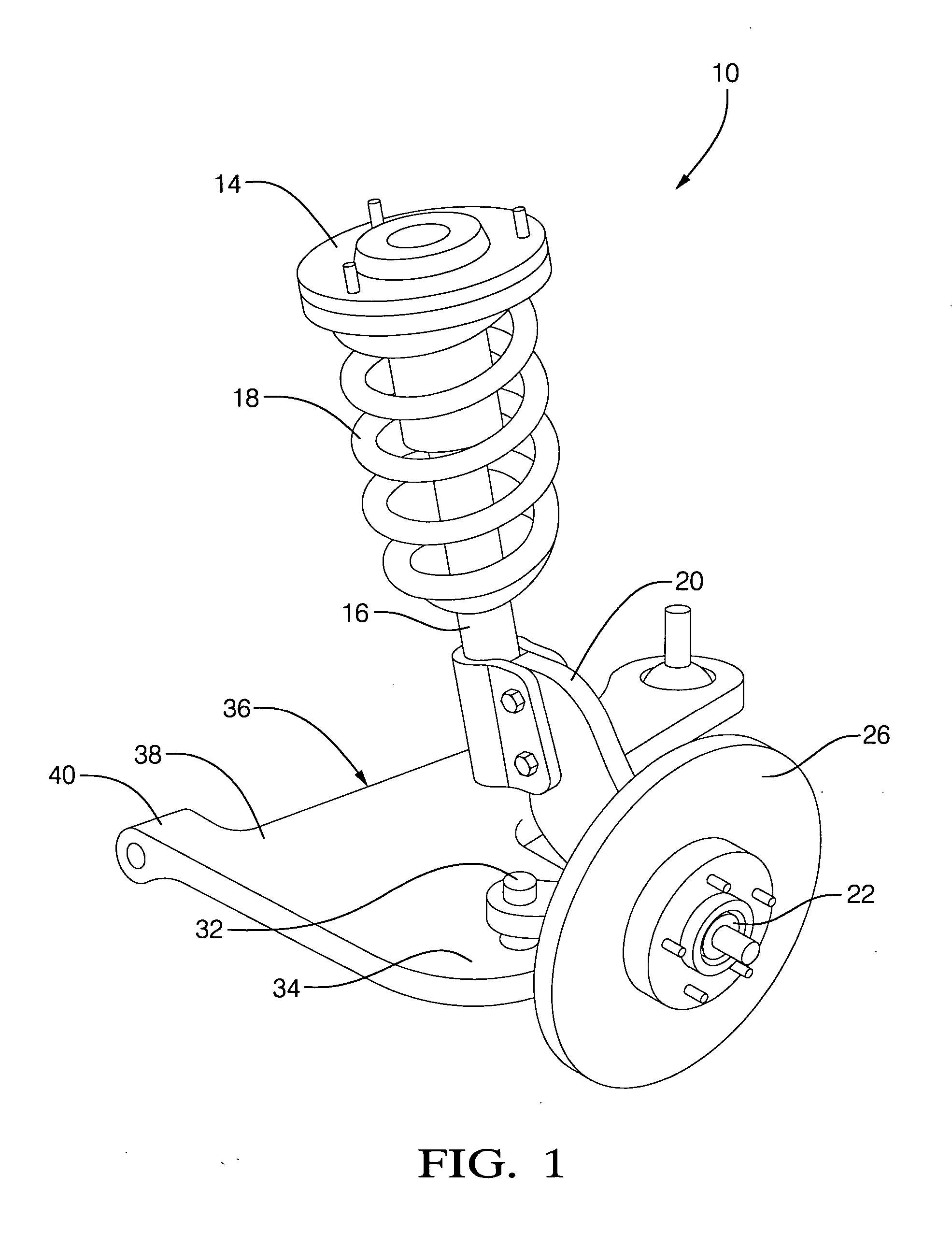
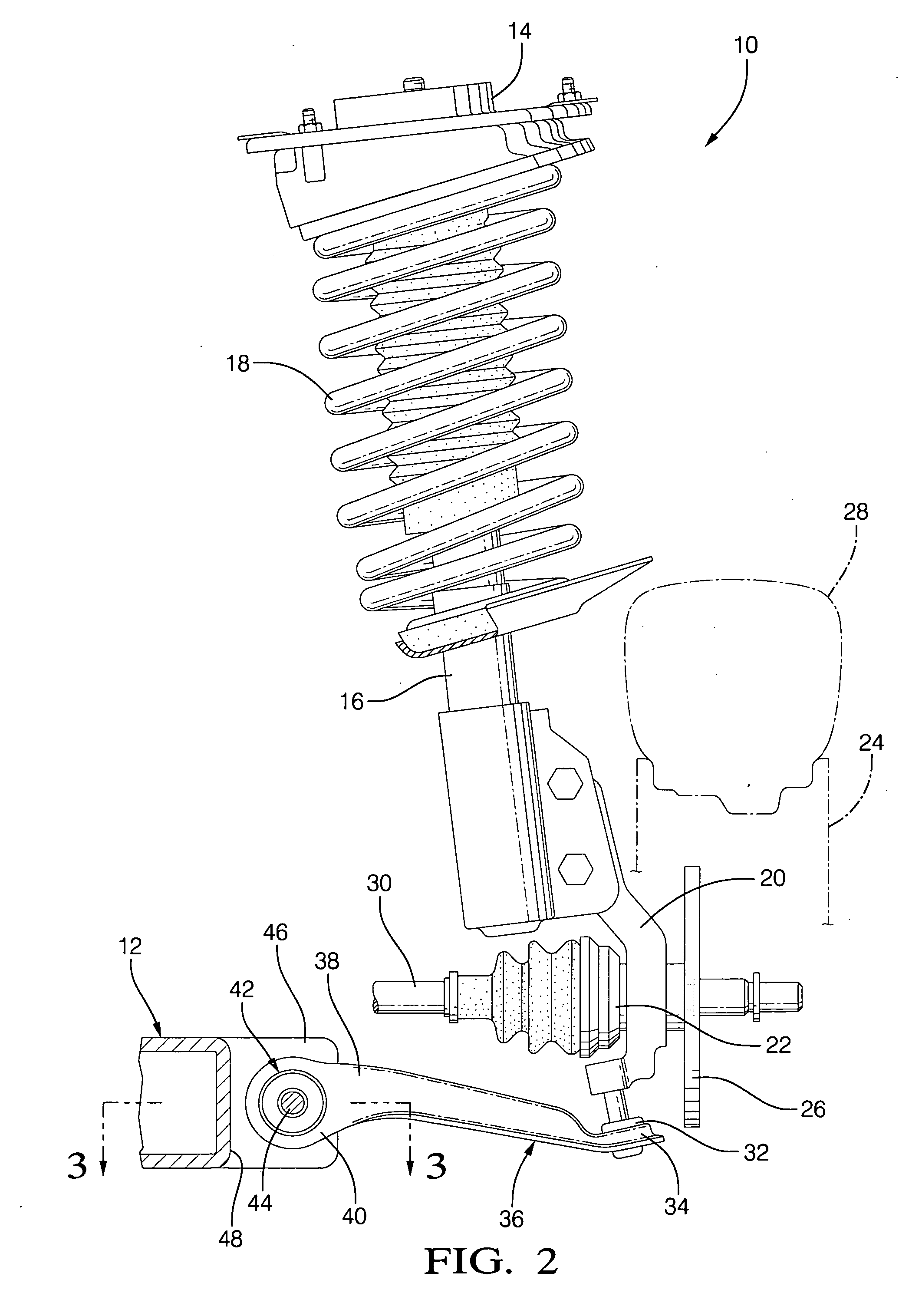
[0045] Referring to FIGS. 1 & 2, an automotive vehicle front wheel drive front suspension assembly 10 includes a shock tower (not illustrated) formed of sheet metal that is rigidly connected to the frame 12 of the host vehicle. Mounted to the shock tower is a strut tower cap 14 which, in turn, is mounted to a McPherson strut 16. The McPhers...
PUM
 Abstract
Description
Claims
Application Information