Orifice flow meters

a flow meter and orifice plate technology, applied in the direction of volume/mass flow measurement, measurement devices, instruments, etc., can solve the problems of affecting the tolerability of flow measurement,

Inactive Publication Date: 2006-10-19
DANIEL INDS
View PDF10 Cites 33 Cited by
  • Summary
  • Abstract
  • Description
  • Claims
  • Application Information

AI Technical Summary

Problems solved by technology

Fluid leakage from the orifice plate assembly may result in erroneous flow measurements.
In such assemblies, if the compression ring side of the orifice plate assembly is accidentally or inadvertently positioned upstream when the assembly is positioned within the orifice flow meter, leakage may occur, thereby detrimentally affecting flow measurements.
In addition, the configuration and arrangement of the orifice plate assembly may impact tolerancing, manufactur

Method used


Image

  • Orifice flow meters
  • Orifice flow meters
  • Orifice flow meters

Examples


Embodiment Construction

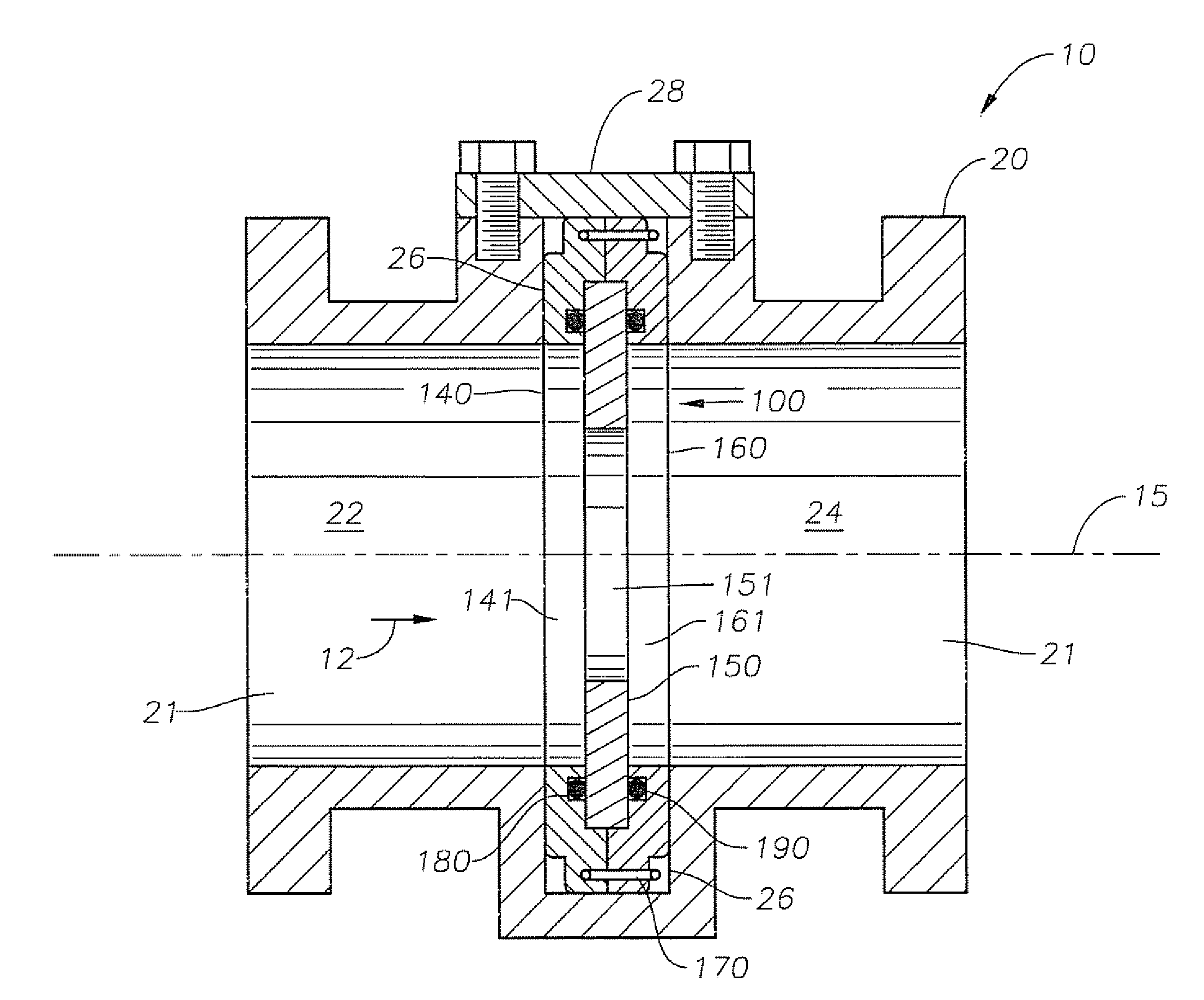
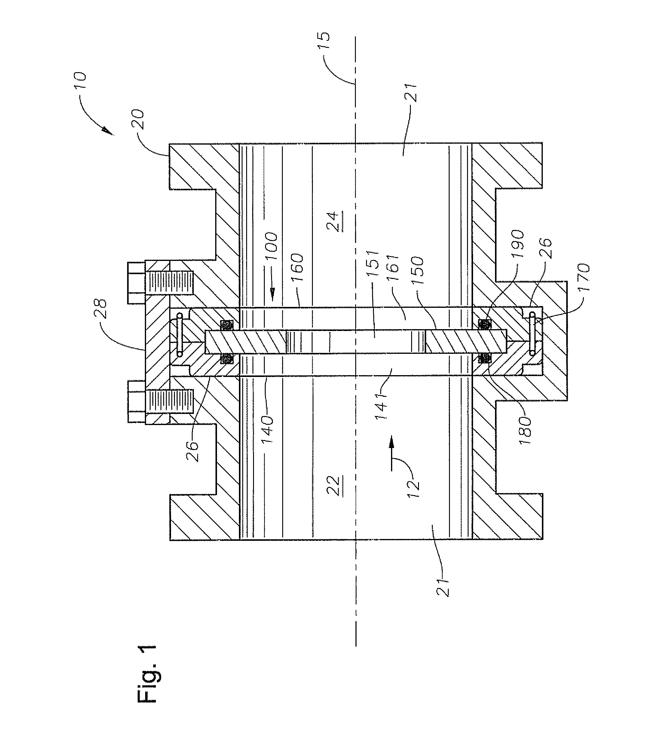
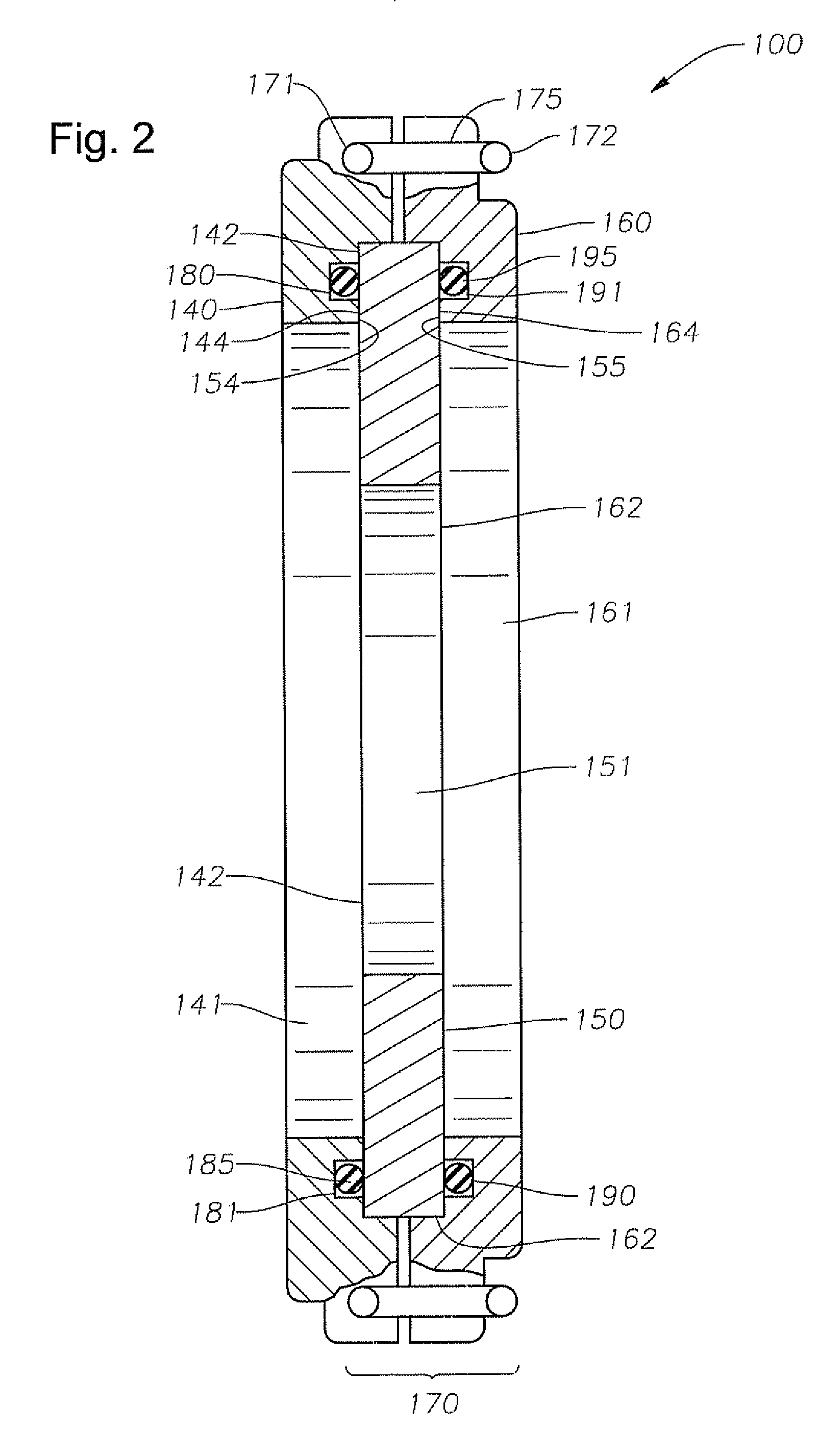
[0012] These and other needs in the art are addressed in one embodiment by an orifice flow meter for measuring flow rate through a conduit. In an embodiment, the orifice flow meter comprises a tubular body having a through passage. In addition, the orifice flow meter comprises an orifice plate assembly disposed within the body across the through passage, wherein the orifice plate assembly includes an orifice plate disposed between a first ring and a second ring, and wherein a first seal assembly is disposed between the first ring and the orifice plate, and a second seal assembly is disposed between the second ring and the orifice plate

[0013] These and other needs in the art are addressed in another embodiment by an orifice plate assembly for an orifice flow meter. In an embodiment, the orifice plate assembly comprises a first ring. In addition, the orifice plate assembly comprises a second ring. Further, the orifice plate assembly comprises an orifice plate disposed between the fir...


PUM


Abstract

An orifice flow meter for measuring flow rate through a conduit. In an embodiment, the orifice flow meter comprises a tubular body having a through passage. In addition, the orifice flow meter comprises an orifice plate assembly removably disposed within the body across the through passage, wherein the orifice plate assembly includes an orifice plate disposed between a first ring and a second ring, and wherein a first seal assembly is disposed between the first ring and the orifice plate, and a second seal assembly is disposed between the second ring and the orifice plate.

Description

CROSS-REFERENCE TO RELATED APPLICATIONS [0001] The present application claims priority to Indian Application Nos. 482 / MUM / 2005; 483 / MUM / 2005; and 484 / MUM / 2005, each filed Apr. 19, 2005. The present application is related to 35 U.S.C. 111(b) provisional application Ser. No. 60 / 722,498 filed Sep. 30, 2005, and entitled Orifice Flow Meters.STATEMENT REGARDING FEDERALLY SPONSORED RESEARCH OR DEVELOPMENT [0002] Not applicable. BACKGROUND OF THE INVENTION [0003] 1. Field of the Invention [0004] The present invention relates generally to flow meters. Particularly, the invention relates to an orifice plate assembly for use in orifice flow meters, [0005] 2. Background of the Invention [0006] Flow rate is the quantification of bulk fluid or gas movement, typically measured as volumetric and mass flow rates. The ability to reliably and accurately measure fluid flow rates may serve an important function in a variety of processes and industries (e.g, chemical processing, oil and gas production, ...

Claims


Application Information

Patent Timeline
IPC IPC(8): G01F1/42
CPCG01F1/42
Inventor KULKARNI, KEDAR A.
Owner DANIEL INDS
Why Eureka
Try Eureka