Connector

a technology of connecting rods and connectors, applied in the direction of electrical equipment, coupling device connections, printed circuits, etc., can solve the problems of buckling of the header body, the dimension of the socket body, and the widthwise direction so as to prevent the deformation of the contact due to buckling, maintain the mechanical strength of the socket body, and prevent the buckling of the header pos

Active Publication Date: 2006-10-19
MATSUSHITA ELECTRIC WORKS LTD
View PDF4 Cites 20 Cited by
  • Summary
  • Abstract
  • Description
  • Claims
  • Application Information

AI Technical Summary

Benefits of technology

[0021] According to such a configuration, the dimension of the connector in widthwise direction can be made smaller than that of the conventional one by eliminating the protruding table of the socket body. Furthermore, for at least the header, the curved portion of the header post is formed into the substantially reverse U-shape and reaches to the concave portion, so that that portion serves as a reinforcement of the header body. Still furthermore, the socket body is reinforced by the reinforcing member inserted or press-fitted. Thus, the mechanical strength of the socket body can be maintained, even though the protruding table of the socket body is eliminated.
[0022] Still furthermore, since the front end of the curved portion of the header post reaches to the concave portion of the header body, the front end of the header post is hooked on the header body. Thus, even when the header body is deformed, the front end of the header post is not lifted from the header body, so that the flaking of the header post from the header body can be prevented.
[0023] Still furthermore, while the

Problems solved by technology

Therefore, the conventional connector has a problem that dimensions in widthwise directions of the

Method used


Image

  • Connector
  • Connector
  • Connector

Examples


Embodiment Construction

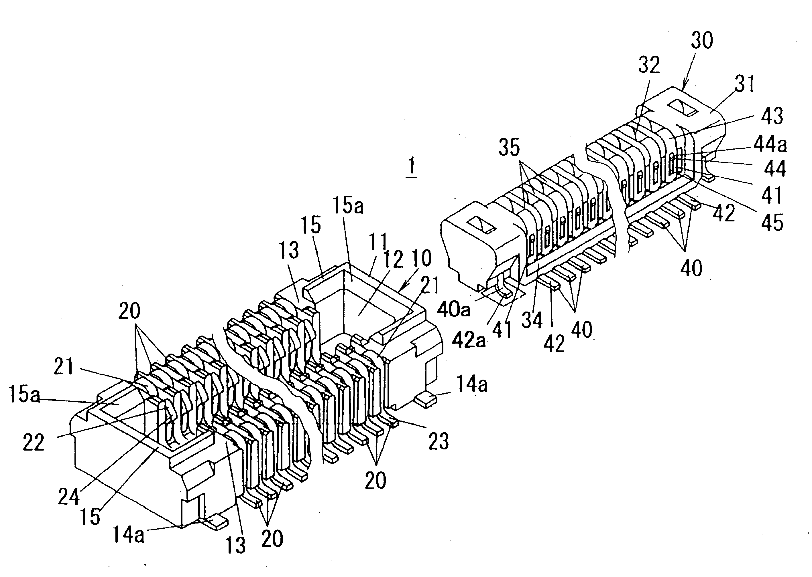
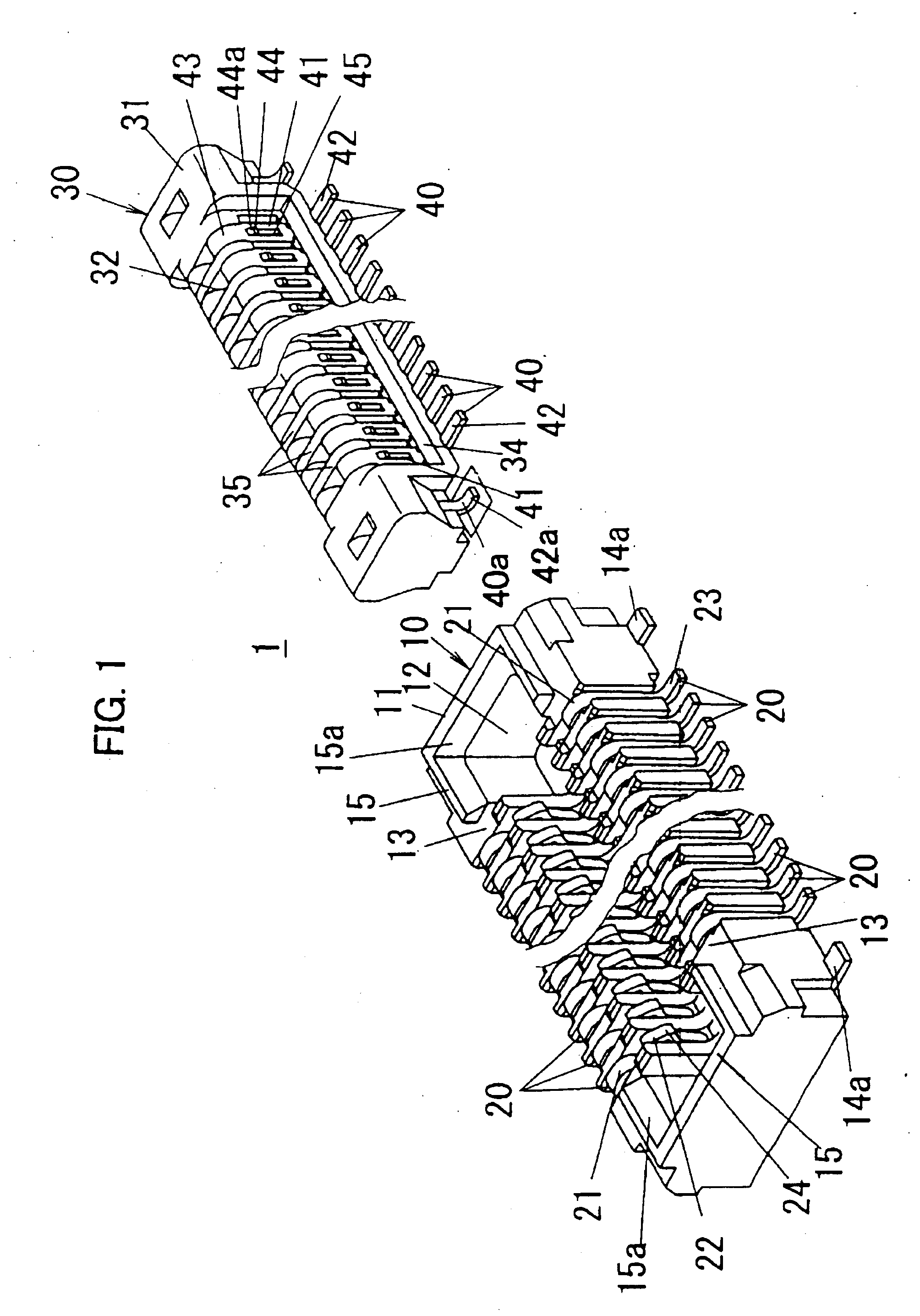
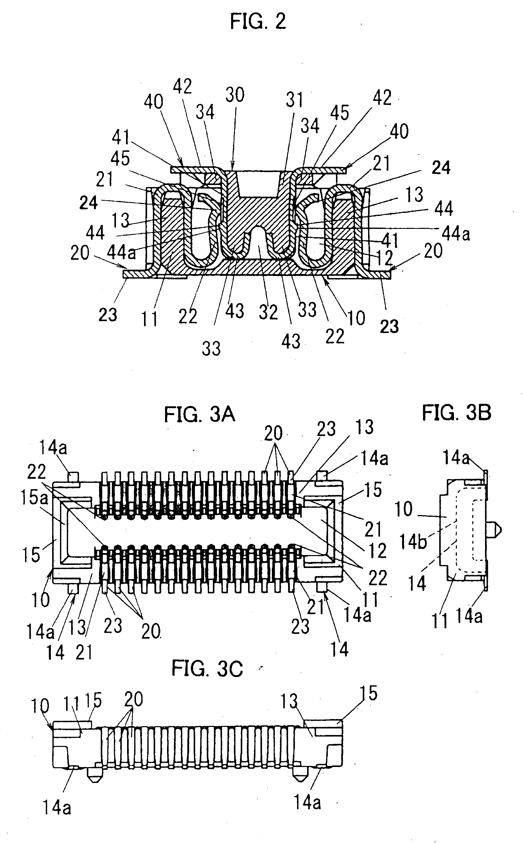
[0034] A connector in accordance with an embodiment of the present invention is described in detail with reference to the drawing. A connector 1 of this embodiment is used, for example, electrically to connect between circuit boards or electronic components and the circuit board in compact electronic equipment such as a mobile phone, and it comprises a socket 10 and a header 30 as shown in FIG. 1. Especially, in a flip phone, the circuit board is divided into a plurality of pieces, and a flexible printed-circuit board (FPC) is used for hinge portion. As an example, such connector 1 is used for electrically connecting an FPC with flexibility and a hard circuit board. For example, the socket 10 is mounted on a conductive pattern formed on the hard circuit board by soldering, and the header 30 is mounted on a conductive pattern on the FPC by soldering. Then, by connecting the header 30 with the socket 10 as shown in FIG. 2, the hard circuit board and the FPC can be electrically connect...


PUM


Abstract

A socket body is reinforced by inserted or press-fitted reinforcing members inserted so that a protruding table is eliminated and a width dimension thereof is reduced. Each socket contact has a first contact portion formed in substantially U-shape for elastically deformable. A header body has concave portions on upper face of the socket body (SIC). Each header post has a second contact portion disposed along a side wall of the header body and to be contacted with a first contact portion of the socket contact, and a curved portion formed in substantially reverse U-shape toward the concave portion from a vicinity of an upper end portion of the side wall of the header body. A curvature radius of the curved portion of the header post is established to be the smallest in a scope that a free end of the first contact portion of the socket contact contacts in the second contact portion side from a peak of the curved portion, and the socket contact is rarely buckled due to scratching with the curved portion.

Description

TECHNICAL FIELD [0001] The present invention relates to a connector comprising a socket and a header for electrically connecting between circuit boards or a circuit board and an electronic component in compact electronic equipment such as a mobile phone. BACKGROUND ART [0002] Conventionally, a connector which is comprised of a socket and a header is provided for electrically connecting between circuit boards, for example, an FPC and a hard board. A conventional connector mentioned in, for example, Japanese Laid-Open Patent Publication No. 2002-8753 is described with reference to FIGS. 7A to 7C, FIG. 8, FIGS. 9A to 9C and FIG. 10. [0003] As shown in FIGS. 7A to 7C and FIG. 8, a socket 50 has a socket body 51 which is formed into a substantially flat rectangular parallelepiped shape by resin molding and a plurality of socket contacts 60 which is arranged on two lines along longitudinal direction of the socket body 51. Seen from front, a protruding table 53 of substantially rectangular...

Claims


Application Information

Patent Timeline
IPC IPC(8): H01R12/00
CPCH01R12/716H01R12/57H01R12/71
Inventor OOKURA, KENJI
Owner MATSUSHITA ELECTRIC WORKS LTD
Why Eureka
Try Eureka