Optical fiber radio transmission system, transmission device, and reception device

a transmission system and optical fiber technology, applied in the direction of optical elements, electromagnetic transceivers, instruments, etc., can solve the problems of inaccurate modulation, narrowed and so as to prevent the deterioration of transmission performance and improve the reception dynamic range of radio signals. , the effect of preventing the loss of linearity of input signals

Inactive Publication Date: 2006-10-26
HASE KAZUTOSHI +2
View PDF4 Cites 103 Cited by
  • Summary
  • Abstract
  • Description
  • Claims
  • Application Information

AI Technical Summary

Benefits of technology

[0026] As described above, according to the present invention, the received dynamic range of radio signals is considerably improved as compared with cases of conventional techniques, and it is possible to optically transmit radio signals while preventing the deterioration of transmission performance and the loss of linearity of an input signal more easily. In addition, the hysteresis effect is employed for switching of amplification/attenuation levels performed by the signal control section. This prevents the levels of

Problems solved by technology

In other words, if the received levels of radio signals fall outside a feasible transmission range as illustrated in FIG. 21, the transmission performance deteriorates.
Thus, there is a problem in that the received dynamic range of radio signals is narrowed because of the limited feasible transmission range.
When intensity modulating a radio signal received at an antenna, as illustrated in (b) of FIG. 22, where the bias current is large, the waveform is distorted at the upper portions thereof because the optical output is saturated

Method used


Image

  • Optical fiber radio transmission system, transmission device, and reception device
  • Optical fiber radio transmission system, transmission device, and reception device
  • Optical fiber radio transmission system, transmission device, and reception device

Examples


first embodiment

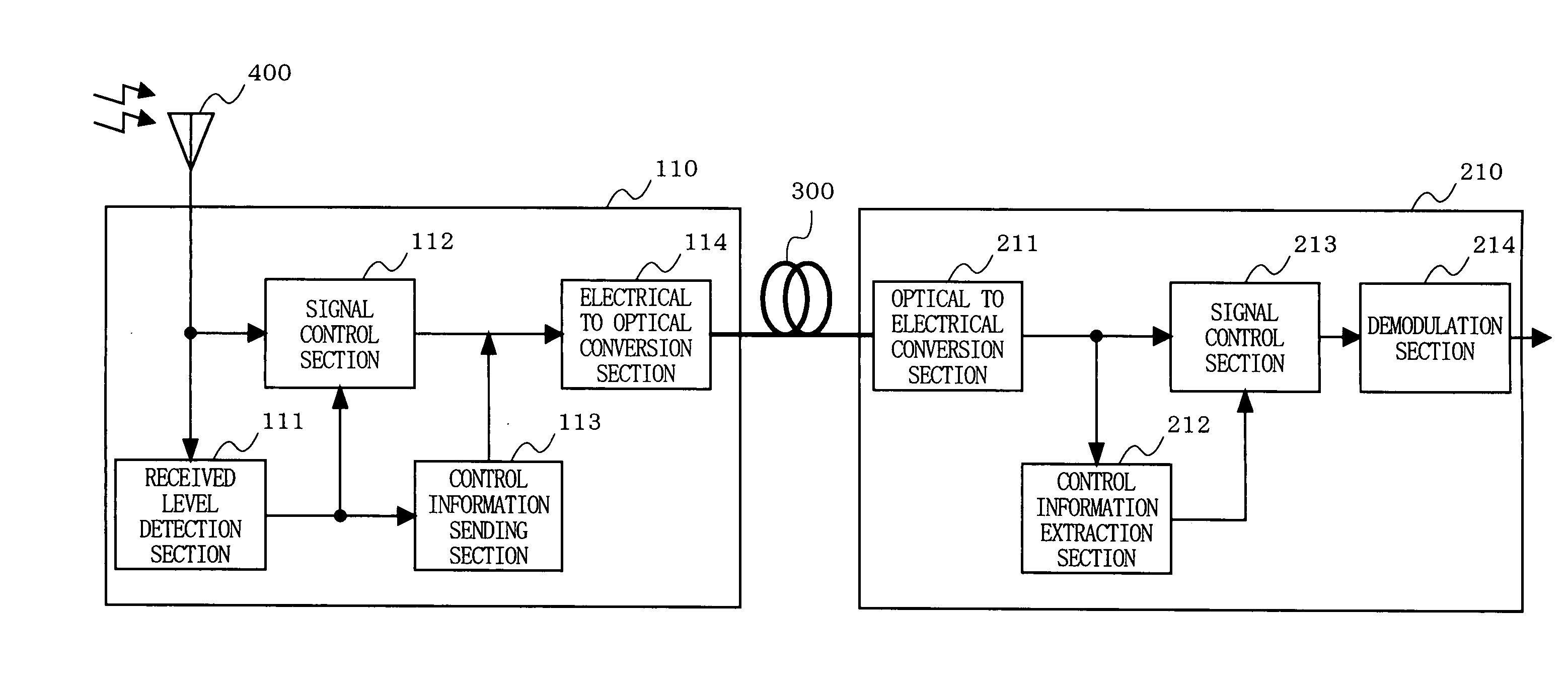
[0085]FIG. 1 is a block diagram illustrating a configuration of an optical fiber radio transmission system according to a first embodiment of the present invention. In FIG. 1, the optical fiber radio transmission system according to the first embodiment has a configuration in which a transmitting unit 110 and a receiving unit 210 are connected via an optical fiber 300. The transmitting unit 110 includes a received level detection section 111, a signal control section 112, a control information sending section 113, and an electrical to optical conversion section 114. The receiving unit 210 includes an optical to electrical conversion section 211, a control information extraction section 212, a signal control section 213, and a demodulation section 214.

[0086] First, operations of the components of the transmitting unit 110 will be described. The received level detection section 111 detects the received level of a radio signal received at an antenna 400, and determines which of a plur...

second embodiment

[0100]FIG. 10 is a block diagram illustrating a configuration of an optical fiber radio transmission system according to a second embodiment of the present invention. In FIG. 10, the optical fiber radio transmission system according to the second embodiment has a configuration in which a transmitting unit 120 and the receiving unit 210 are connected via the optical fiber 300. The transmitting unit 120 includes a hysteresis received level detection section 121, the signal control section 112, the control information sending section 113, and the electrical to optical conversion section 114. The receiving unit 210 includes the optical to electrical conversion section 211, the control information extraction section 212, the signal control section 213, and the demodulation section 214.

[0101] As is apparent from FIG. 10, the optical fiber radio transmission system according to the second embodiment differs from the optical fiber radio transmission system according to the above-described ...

third embodiment

[0106]FIG. 12 is a block diagram illustrating a configuration of an optical fiber radio transmission system according to a third embodiment of the present invention. In FIG. 12, the optical fiber radio transmission system according to the third embodiment has a configuration in which a transmitting unit 130 and the receiving unit 230 are connected via the optical fiber 300. The transmitting unit 130 includes the received level detection section 111, the signal control section 112, a control voltage conversion section 131, a V-f conversion section 132, and the electrical to optical conversion section 114. The control voltage conversion section 131 and the V-f conversion section 132 correspond to the control information sending section 113, which has been described in the above-described first embodiment. The receiving unit 230 includes the optical to electrical conversion section 211, a lowpass filter (LPF) 231, an f-V conversion section 232, a highpass filter (HPF) 233, the signal c...


PUM


Abstract

An optical fiber radio transmission system is provided which is capable of considerably improving the received dynamic range of radio signals and, in addition, is capable of optically transmitting radio signals while preventing the deterioration of transmission performance and the loss of linearity of an input signal more easily. A received level detection section 111 detects which one of predetermined levels, i.e., Level I, Level II, and Level III, the received level of a radio signal received by an antenna 400 falls under. A signal control section 112 performs an amplification/attenuation process on the radio signal in accordance with the detected level. A control information sending section 113 superimposes control information indicating the detected level on a primary signal obtained after the amplification/attenuation process. This signal is converted to an optical signal and transmitted. An optical to electrical conversion section 211 converts the optical signal received from a transmitting unit to an electrical signal. A control information extraction section 212 extracts the level from the control information, which has been superimposed on the primary signal. A signal control section 213 performs an amplification/attenuation process on the primary signal in accordance with the extracted level.

Description

TECHNICAL FIELD [0001] The present invention relates to an optical fiber radio transmission system, a transmitting unit, and a receiving unit, and more particularly to an optical fiber radio transmission system, including a transmitting unit (e.g., a remote station) for receiving radio signals via an antenna and a receiving unit (e.g., a base station) connected to each other via an optical fiber, for optically transmitting radio signals via the optical fiber, the system being a transmission system in the optical communications field. BACKGROUND ART [0002] A conventional, generally known configuration of an optical fiber radio transmission system is illustrated in FIG. 20. A transmitting unit 510 and a receiving unit 610 are connected to each other via an optical fiber 700. In the transmitting unit 510, a radio signal received at an antenna 800 is amplified by an amplifier 511 and converted by an electrical to optical conversion section 512 to an optical signal, and thereafter the op...

Claims


Application Information

Patent Timeline
IPC IPC(8): G02B6/00H04B10/40H03F3/08H04B10/07H04B10/2507H04B10/2575H04B10/293H04B10/50H04B10/54H04B10/564H04B10/58H04B10/60
CPCH04B10/25759H03F3/08
Inventor HASE, KAZUTOSHIYAMAMOTO, HIROAKIUTSUMI, KUNIAKI
Owner HASE KAZUTOSHI
Why Eureka
Try Eureka