Automatic self cleaning bladder relief with battery pad system
Inactive Publication Date: 2006-10-26
HARVIE MARK R
View PDF14 Cites 6 Cited by
Summary
Abstract
Description
Claims
Application Information
AI Technical Summary
This helps you quickly interpret patents by identifying the three key elements:
Problems solved by technology
Method used
Benefits of technology
[0024] the present invention also provides for ease of set up, use, urine storage and disposal; and
[0025] the present invention also prov
Problems solved by technology
For example U.S. Pat. No. 4,886,508 (Washington, 1989) discloses a ladies' external catheter assembly, however this device does not use a vacuum pump for drainage or utilize a moisture sensor.
Also U.S. Pat. No. 4,610,675 (Triunfol, 1986) teaches a device for collecting fluid discharged from female organs that is designed solely for incontinent women, not female aircrew members and the design includes a pad, vacuum pump and liquid sensor, however, the pad is more invasive because it is formed of plastic and has ridges to move the labia to an open position for free flow of liquid.
There are no acceptable bladder relief systems for incontinent adults.
Many incontinent males use commercially available diapers, which cannot contain urine from multiple urinations, and become heavy and uncomfortable when wet.
While each of these prior art patents disclose bladder relief systems which fulfill their respective particular objectives and requirements, and are most likely quite functional for their intended purposes, it will be noticed that none of the prior art cited disclose an apparatus and/or method that allow a user the comfort of automatic operation and large volume capacity.
There is also no acceptable bladder relief system for male aircrew members flying extended flight operations in single or dual-seat fighter and reconnaissance aircraft that do not have toilet facilities.
During this pro
Method used
Image
Click on the blue label to locate the original text in one second.
Reading with bidirectional positioning of images and text.
Examples
Embodiment Construction
I. Preferred Embodiments
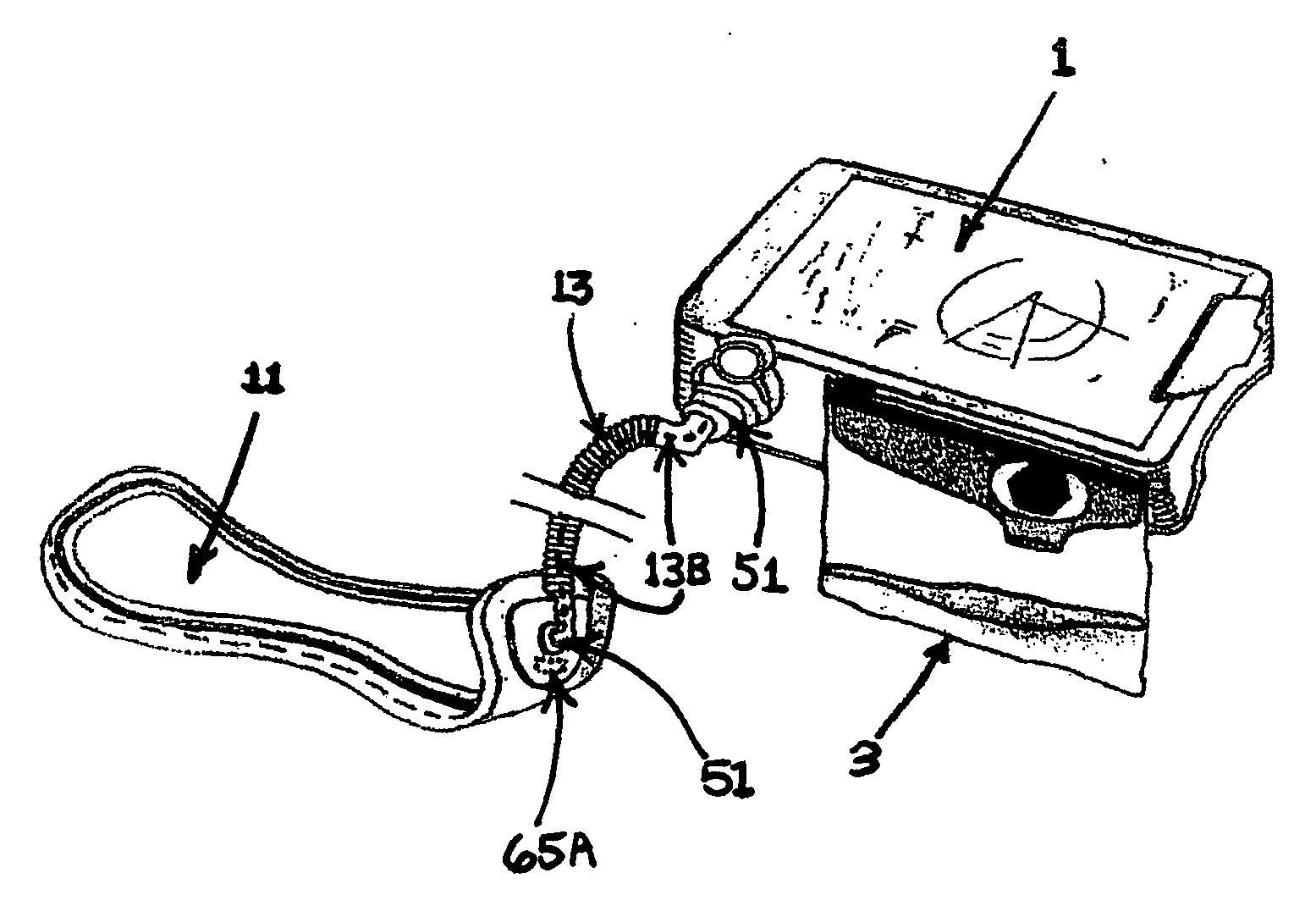
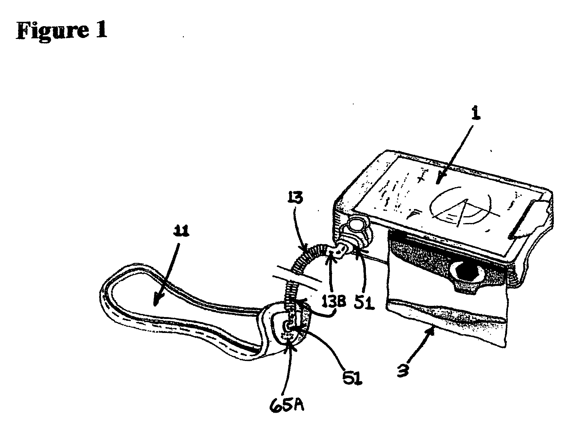
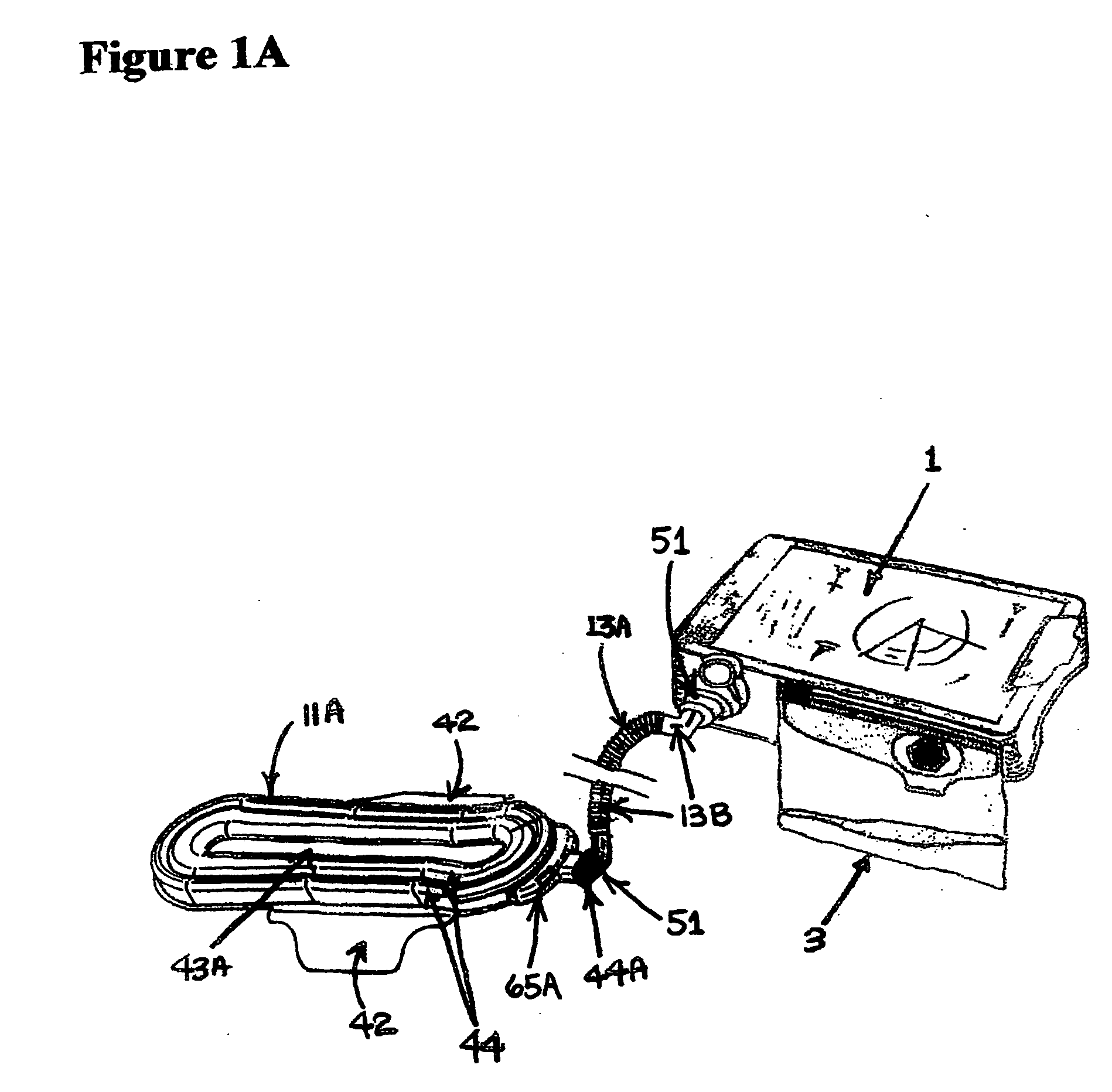
[0040] With reference now to the drawings, and in particular to FIGS. 1-9 thereof, a new and novel apparatus for an automatic bladder relief system embodying the principles and concepts of the present invention and generally designated collectively comprising two main components in the female user embodiment by the reference numeral 1 and 11 in FIG. 1, and in the male user embodiment by the reference numeral 1 and 57 in FIG. 4.
List and Description of:
GENERAL DESCRIPTION OF REFERENCE NUMERALS IN THE DESCRIPTION AND DRAWINGS
[0041] Any actual dimensions listed are those of the preferred embodiment. Actual dimensions or exact hardware details and means may vary in a final product or most preferred embodiment and should be considered means for so as not to narrow the claims of the patent. [0042] (1) Suction Control Unit [0043] (1A) Air Pump [0044] (2) Suction Vacuum Pump [0045] (3) Urine Collection Bag [0046] (5) DC Motor [0047] (7) Rechargeable Battery Pack [...
PUM
Abstract
This invention is an automatic or semi-automatic bladder relief system which increases sanitation and comfort for users requiring a means to dispose of urine in the absence of sanitary facilities, such as aircraft pilots and incontinent individuals. This invention incorporates an inflatable urine collection means that may be deflated after use. The power unit incorporates a battery that is integrated into a disposable urine storage bag or into a disposable female pad or male cup. This invention utilizes a disposable urine storage bag with an isolated cleaning fluid chamber with a directional valve and pump system automatically rinsing and sanitizing the pump, hoses, collection means and the user with a cleaning fluid stored in the cleaning fluid chamber of the disposable urine storage bag. The disposable urine storage bag contains absorbent polymer crystals absorbing the urine as it is deposited in the bag during use.
Description
CROSS REFERENCE TO RELATED APPLICATION [0001] This Application is a Continuation-In-Part of the Co-Pending patent application U.S. Ser. No. 10 / 885,355, filed on Jul. 6, 2004, which in turn is a Continuation-In-Part of the Co-Pending patent application U.S. Ser. No. 10 / 418,852, filed Apr. 18, 2003 (now issued U.S. Pat. No. 6,918,899), which in turn is a Continuation-In-Part of patent application U.S. Ser. No. 10 / 369,240 filed Feb. 19, 2003 (now issued U.S. Pat. No. 6,706,027) and claiming priority from Provisional Patent Application No. 60 / 359,672 which was filed on Feb. 26, 2002.BACKGROUND ART [0002] The use of human urinary collection and disposal systems is known in the prior art. For example U.S. Pat. No. 4,886,508 (Washington, 1989) discloses a ladies' external catheter assembly, however this device does not use a vacuum pump for drainage or utilize a moisture sensor. Also U.S. Pat. No. 4,610,675 (Triunfol, 1986) teaches a device for collecting fluid discharged from female organ...
Claims
Application Information
Patent Timeline
Application Date:The date an application was filed.
Publication Date:The date a patent or application was officially published.
First Publication Date:The earliest publication date of a patent with the same application number.
Issue Date:Publication date of the patent grant document.
PCT Entry Date:The Entry date of PCT National Phase.
Estimated Expiry Date:The statutory expiry date of a patent right according to the Patent Law, and it is the longest term of protection that the patent right can achieve without the termination of the patent right due to other reasons(Term extension factor has been taken into account ).
Invalid Date:Actual expiry date is based on effective date or publication date of legal transaction data of invalid patent.