
Hanger bar centering mechanism

a technology of hanging mechanism and recessed downlight, which is applied in the direction of curtain suspension device, lighting and heating apparatus, lighting support device, etc., can solve the problems of poor installation quality, time-consuming and difficult to obtain consistently, and the positioning of the fram

Inactive Publication Date: 2006-11-02
PHILIPS LIGHTING NORTH AMERICA CORPORATION
View PDF84 Cites 64 Cited by
  • Summary
  • Abstract
  • Description
  • Claims
  • Application Information

AI Technical Summary

Benefits of technology

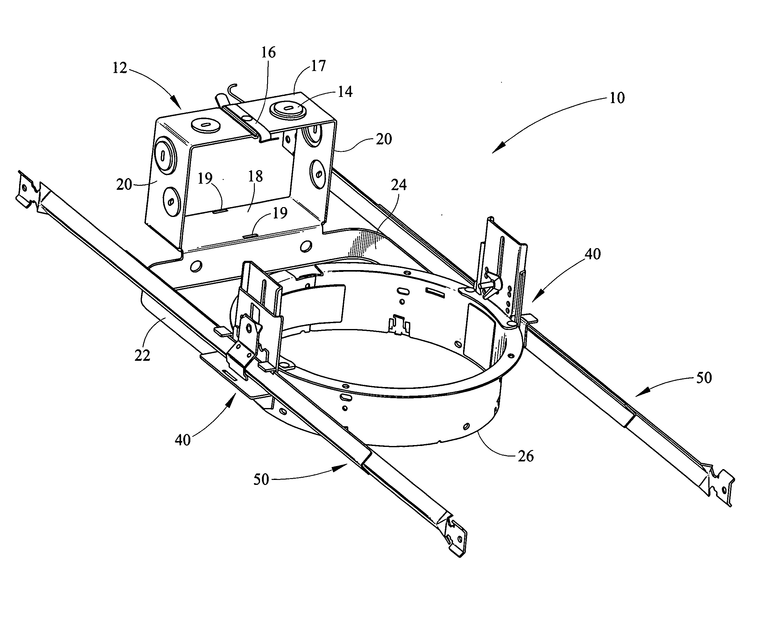
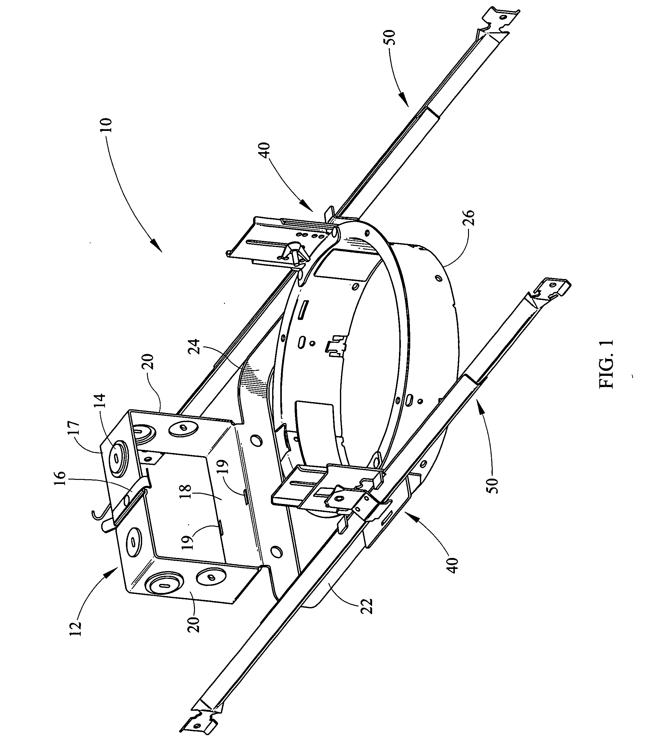
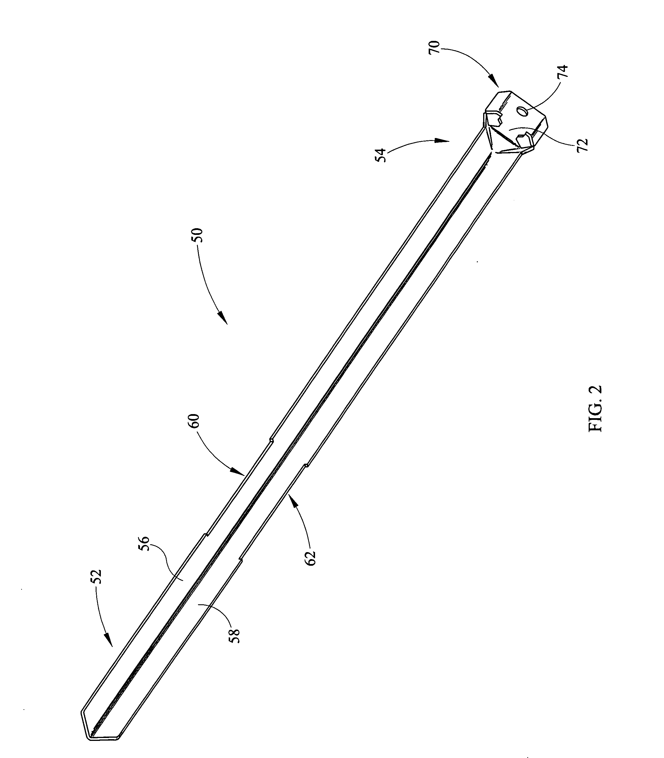
[0011] According to a first embodiment of the present invention, a hanger bar centering mechanism comprises a first elongate member having a first end and a second end, a second elongate member having a first end and a second end, the first and second members are symmetrically formed, the first and second elongate members each have at least one corresponding notch portion, and the notch portions are aligned for providing positive feedback when the first and second members are slidably positioned relative to each other in a preselected specific position.

Problems solved by technology

One difficulty associated with the installation of recessed lighting frame-in kits is the positioning of the frame-in kit in a centered position between joists or suspended ceiling members quickly in a repetitive and consistent manner.
For example, when one light in a row of recessed lights is out of alignment, the installation looks poor in quality and is undesirable for a customer.
The result is an aesthetically pleasing installation which is time consuming and difficult to obtain consistently.

Method used


Image

  • Hanger bar centering mechanism
  • Hanger bar centering mechanism
  • Hanger bar centering mechanism

Examples


Embodiment Construction

[0029] It should be understood that the invention is not limited in its application to the details of construction and the arrangement of components set forth in the following description or illustrated in the drawings. The invention is capable of other embodiments and of being practiced or of being carried out in various ways. Also, it is to be understood that the phraseology and terminology used herein is for the purpose of description and should not be regarded as limiting. The use of “including,”“comprising,” or “having” and variations thereof herein is meant to encompass the items listed thereafter and equivalents thereof as well as additional items. Unless limited otherwise, the terms “connected,”“coupled,” and “mounted,” and variations thereof herein are used broadly and encompass direct and indirect connections, couplings, and mountings. In addition, the terms “connected” and “coupled” and variations thereof are not restricted to physical or mechanical connections or couplin...


PUM


Abstract

A hanger bar centering mechanism comprises a first elongate member having a first end and a second end, a second elongate member having a first end and a second end, the first and second members are symmetrically formed, the first and second elongate members each have at least one corresponding notch portion, and the notch portions are aligned for providing positive feedback when the first and second members are slidably positioned relative to each other in a preselected specific position.

Description

CROSS REFERENCES TO RELATED APPLICATIONS [0001] None. STATEMENT REGARDING FEDERALLY SPONSORED RESEARCH OR DEVELOPMENT [0002] None. REFERENCE TO SEQUENTIAL LISTING, ETC. [0003] None. BACKGROUND [0004] 1. Field of the Invention [0005] The present invention provides a centering mechanism for a recessed downlight frame-in kit. More specifically, the present invention comprises a hanger bar centering mechanism for a recessed downlight frame-in kit. [0006] 2. Description of the Related Art [0007] Recessed downlight fixtures have become increasingly popular for residential and commercial use. One reason for the increased popularity is that the recessed downlight fixtures meet a wide range of interior lighting requirements while also being aesthetically pleasing. Further these recessed downlight fixtures may be installed in new constructions as well as existing ceilings and therefore are liked by installers. Typically, ceiling-mounted recessed downlight fixtures comprise a frame or frame-in...

Claims


Application Information

Patent Timeline
IPC IPC(8): B42F13/00
CPCH02G3/125F21V21/04
Inventor RIPPEL, GRAHAM MICHAEL
Owner PHILIPS LIGHTING NORTH AMERICA CORPORATION
Learn More