

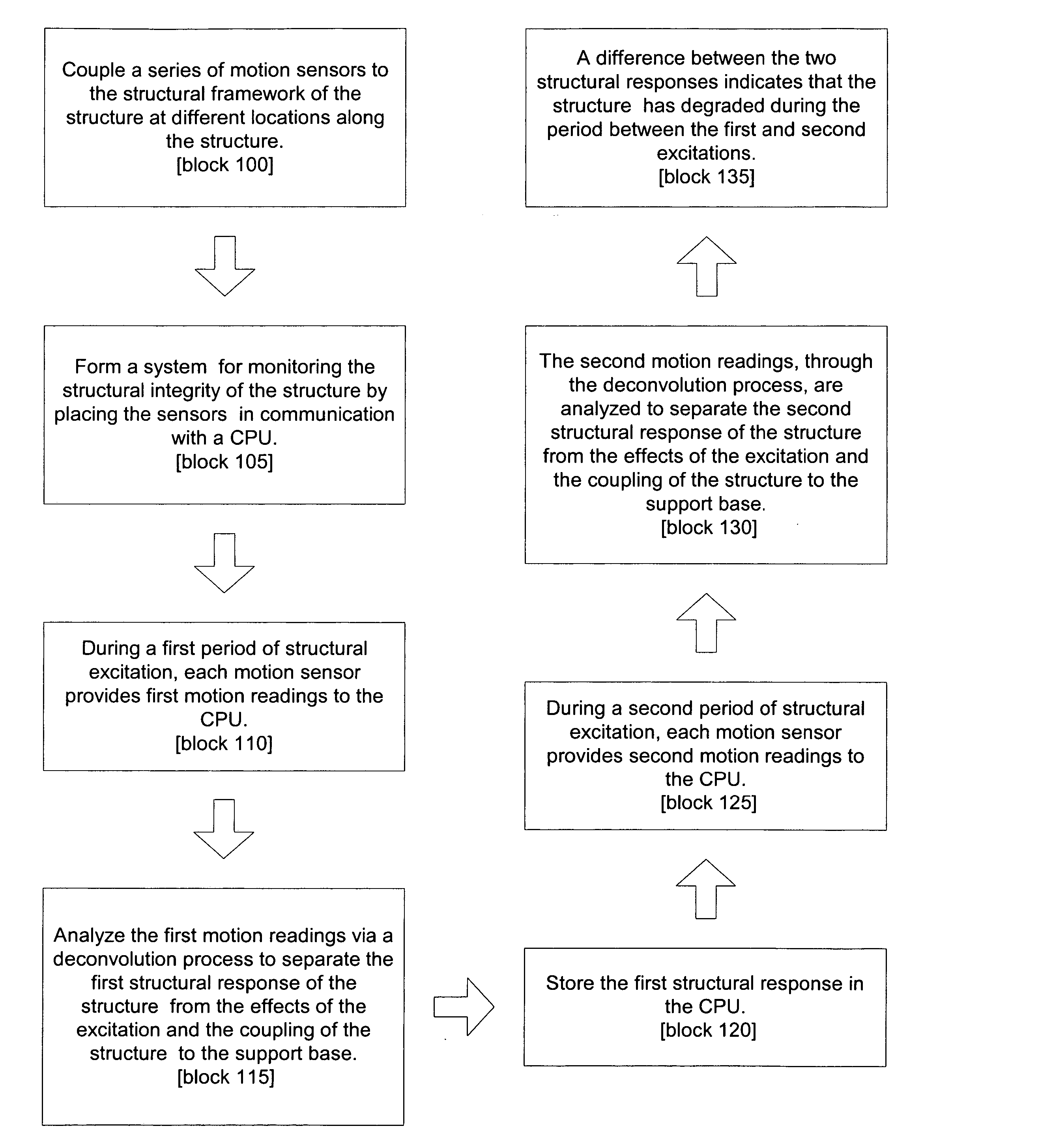
System for and method of monitoring structural integrity of a structure
a technology of structural integrity and monitoring system, applied in the direction of measuring device, scientific instruments, instruments, etc., can solve the problems of difficult to determine whether the structural framework of a building, crane, etc., is still structurally sound
- Summary
- Abstract
- Description
- Claims
- Application Information
AI Technical Summary
Benefits of technology
Problems solved by technology
Method used
Image

Examples
Embodiment Construction
[0040] I. Introduction.
[0041] The response (i.e., motion) of a building caused by natural or man-made shaking is largely a function of the mechanical properties of the building. These mechanical properties include the building's shear wave velocity (i.e., the rate at which shear waves propagate through the building) and the attenuation of the building (i.e., the building's ability to attenuate the wave energy resulting from the natural or man-made shaking). The building's shear wave velocity, together with the geometry of the building, controls the resonant frequencies of the building. The attenuation of the building determines the rate of energy dissipation in the building, which in turn controls the motion of the building for a given excitation.
[0042] A complicating factor in the response of a building to shaking is that this response depends both on the properties of the building, as well as on the nature of the coupling to the subsurface. It has been documented that the resona...
PUM
 Abstract
Description
Claims
Application Information