
Method and device for lining a pipe conduit or a channel

Active Publication Date: 2006-11-16
SCHWERT SIEGFRIED
View PDF9 Cites 23 Cited by
  • Summary
  • Abstract
  • Description
  • Claims
  • Application Information

AI Technical Summary

Benefits of technology

[0010] The object of the present invention therefore is so to improve the known method for lining a pipe conduit or a channel with a sealing inner lining having a tubing consisting of a woven fabric, meshing, felt, knitted fabric or non-woven, adhering

Problems solved by technology

However, this is a process lasting several hours, the filling and distribution of the adhesive (approximately 1000 kg with a nominal diameter of DN 300 and a renovation length of 600 m) alone require more than an hour and the average advancing speed of the tubing is roughly 6 m per minute.
Since with renovation of a pipe conduit or a channel taking place in this manner, normal operation has to be interrupted for this period, this can be connected with considerable operating restriction

Method used


Image

  • Method and device for lining a pipe conduit or a channel
  • Method and device for lining a pipe conduit or a channel
  • Method and device for lining a pipe conduit or a channel

Examples


Example

DETAILED DESCRIPTION OF THE DRAWINGS AND THE PRESENTLY PREFERRED EMBODIMENTS

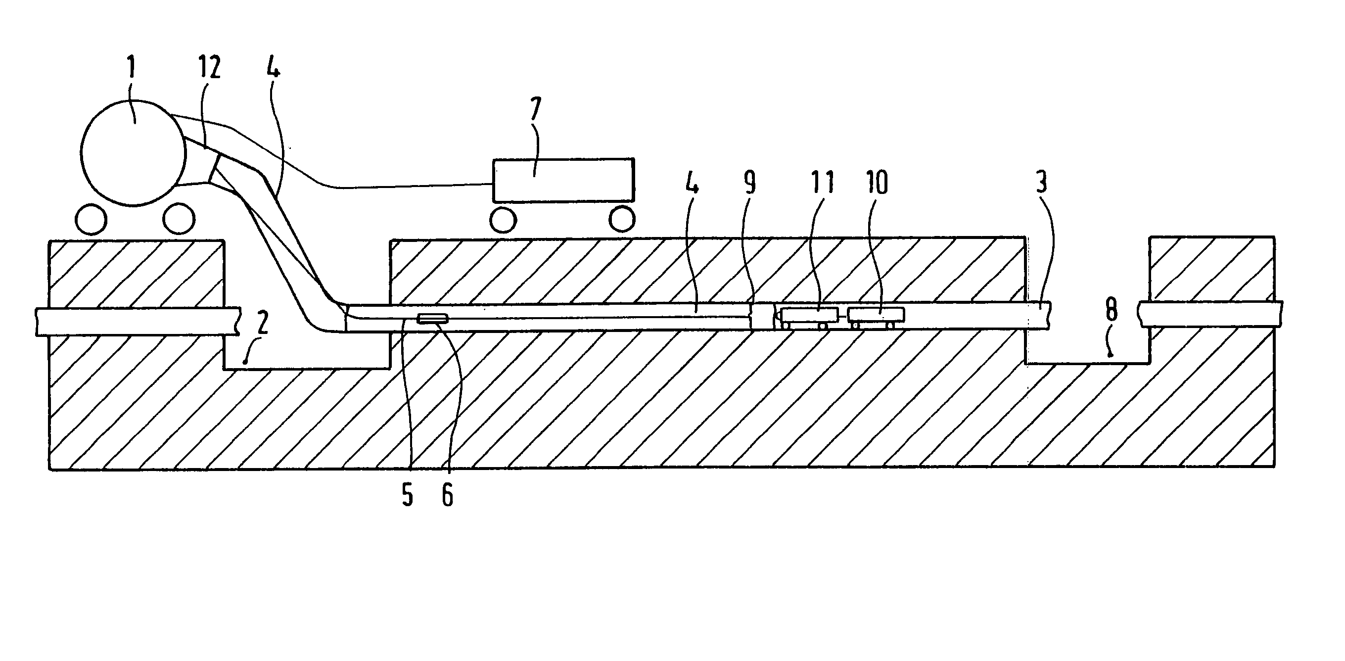
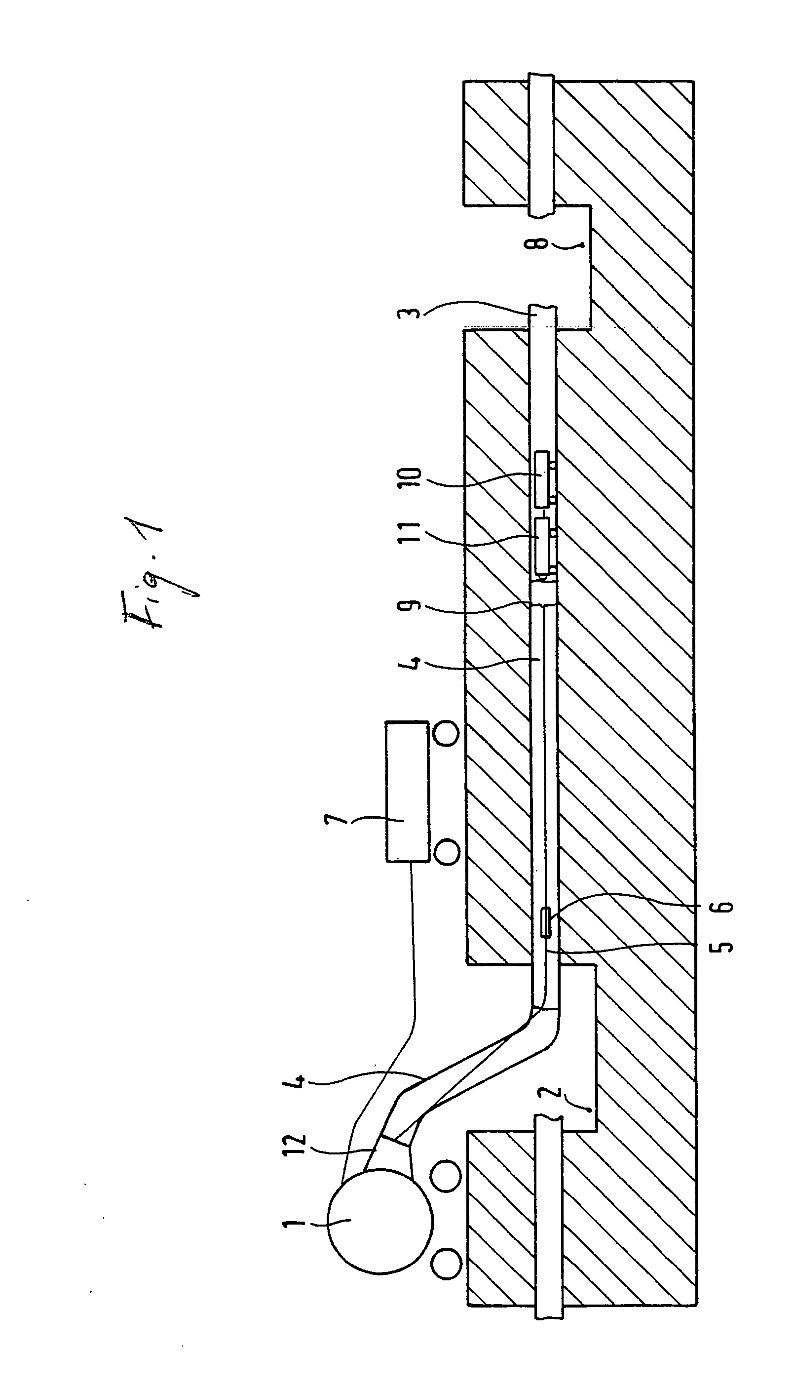
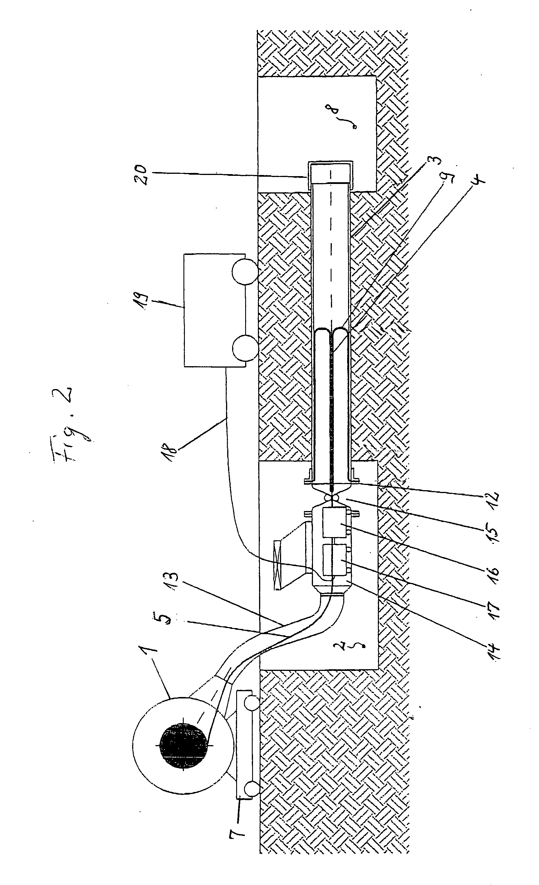
[0058] As shown in FIG. 1, a mobile rotary drum 1 is located in the immediate vicinity of an installation trench 2 for a pipe conduit 3 to be renovated. At the beginning of the renovation process, there is located in the rotary drum 1 in a coiled state a textile tubing 4 at least 100 m in length, preferably more than 500 m, which contains in its interior a metered amount of slow-curing adhesive. Furthermore, communicating with the textile tubing 4 is a likewise coiled retaining tape 5 of roughly the same length, the two being coupled-together via a connecting piece 6. A mobile air compressor 7 is connected to the rotary drum 1 and generates in the latter an increased pressure in relation to the atmosphere.

[0059] The pipe conduit 3 formed from metal, preferably steel, grey cast iron or ductile cast iron, plastics material, preferably PVC or GRP (glass-fibre reinforced plastic) or mineral material, preferabl...


PUM

PropertyMeasurementUnit
Lengthaaaaaaaaaa
Timeaaaaaaaaaa
Timeaaaaaaaaaa

Abstract

A method for lining a pipe conduit with a coated textile tubing that adheres to the inner walls of the pipe conduit by means of an adhesive. The coated textile tubing can be filled with a long pot life adhesive and the textile tubing turned inside out (inverted) while being introduced into the pipe conduit. A fast curing adhesive is substantially simultaneously applied to the inner wall of the pipe conduit in as short a distance as possible to the moving tubing inversion point. The introduced tubing is then subjected to an inner pressure to force the tubing into contact with the pipe inner wall until the fast curing adhesive has cured. Alternatively, an impregnated textile tubing can be substituted for the tubing filled with the long pot life adhesive. As a further alternative, conditions are controlled to cause curing of the adhesive only in the inverted portion of the tubing.

Description

CROSS-REFERENCE TO RELATED APPLICATIONS [0001] This application is a continuation-in-part of U.S. patent application Ser. No. 10 / 148,315, filed May 29, 2002.BACKGROUND OF THE INVENTION [0002] The present invention relates to a method for lining a pipe conduit or a channel with a sealing inner lining having a tubing, and a device for accomplishing this method. [0003] In U.S. Pat. No. 4,368,091 is disclosed a method for lining the inner surface of a pipe conduit with a flexible tubular lining material, using liquid resin serving as the adhesive. This method has the following steps: [0004] a) filling a metered amount of the resin into the tubular lining material, evenly distributed over its length, [0005] b) annularly securing one end of the lining material which contains the liquid resin in its interior, to the one end of the pipe conduit, [0006] c) exerting pressure with the aid of a pressure medium on the lining material in such a way that at a turning point, which is formed behind ...

Claims


Application Information

Patent Timeline
IPC IPC(8): B29C65/00B29C63/36F16L55/165
CPCF16L55/1651B29C63/36
Inventor SCHWERT, SIEGFRIED
Owner SCHWERT SIEGFRIED
Learn More