
Apparatus for securing a dangerous zone

Inactive Publication Date: 2006-11-16
SICK AG
View PDF1 Cites 0 Cited by
  • Summary
  • Abstract
  • Description
  • Claims
  • Application Information

AI Technical Summary

Benefits of technology

[0007] It is an object of the present invention to provide an improved system for securing dangerous zones, particularly such zones at automatically operating machines, which are less costly and provide a higher degree of safety than prior art systems.

Problems solved by technology

This system has significant disadvantages.
Following the rough alignment of the picture-taking unit, in order to include the defined target, costly further alignment and processing is necessary.
This known system has the further disadvantage that it attains the required redundancy by duplicating the system to assure that the picture-taking unit and the defined target operate properly at all times to adequately protect the danger zone that is being monitored.
This greatly increases the costs of such systems.
In addition, this known system cannot have a defined target in the area of the picture-taking unit and the light source.
As a result, dead zones are formed in these areas which cannot be monitored and which therefore constitute unprotected portions of the danger zone.

Method used


Image

  • Apparatus for securing a dangerous zone
  • Apparatus for securing a dangerous zone
  • Apparatus for securing a dangerous zone

Examples


Embodiment Construction

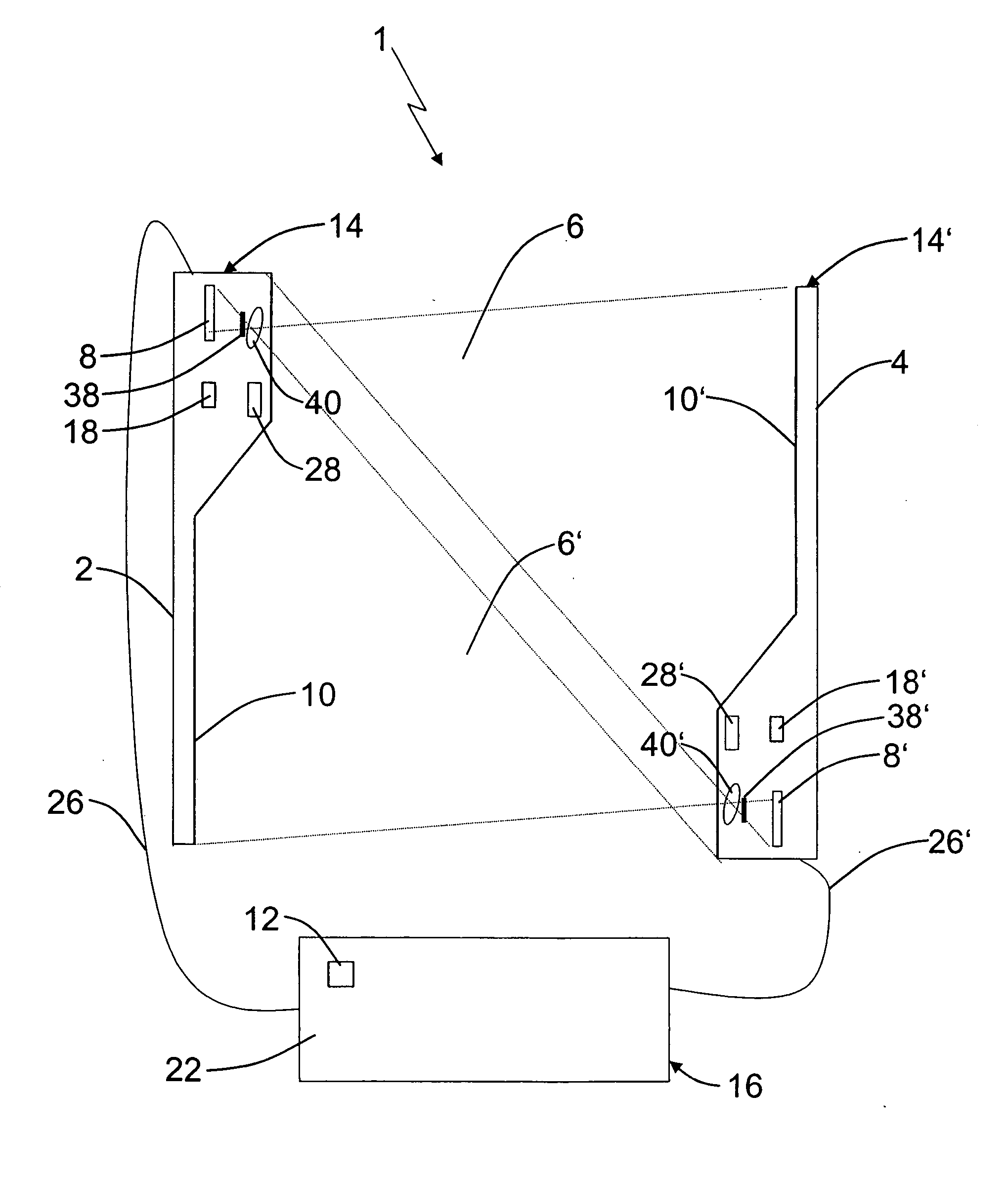
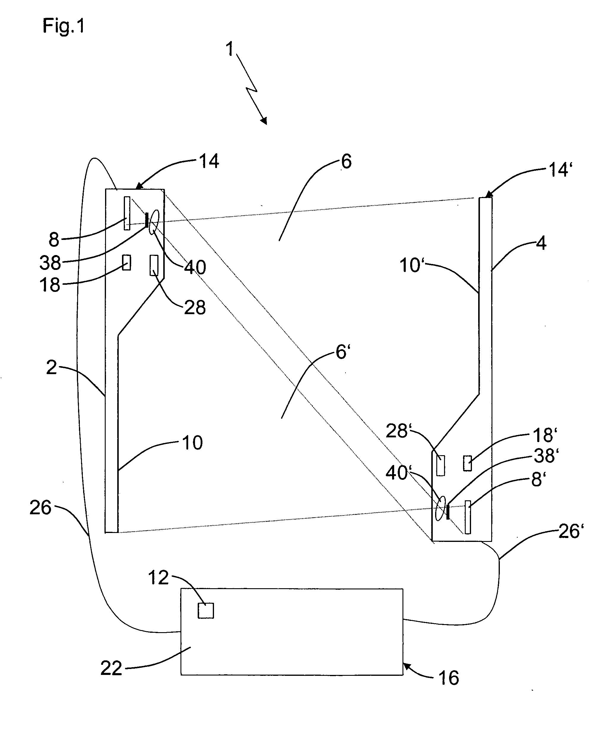
[0033]FIG. 1 shows an apparatus or a system 1 for securing a danger zone in accordance with the present invention in the form of an automatically operating machine. The system of the illustrated embodiment has a first optical unit 2 and a second optical unit 4. The optical units 2 and 4 are respectively arranged in a housing 14 and 14′. Information channels 26, 26′ connect the two optical units 2, 4 with a processing and switching unit 22. The optical units 2, 4 include a picture-taking unit 8, 8′, a marking 10, 10′, a lighting unit 28, 28′, a device 18, 18′ for changing an operating parameter of the lighting unit, and a receiving optic 40, 40′, respectively. In addition, the optical units 2, 4 respectively include an optical aperture 38, 38′. These optical components are arranged and aligned inside the respective housing 14, 14′. When the optical system 1 of the present invention is installed, only the optical units 2, 4 have to be aligned with respect to each other.

[0034] The two...


PUM


Abstract

Apparatus for monitoring a dangerous zone with an optical system for monitoring a protected field has at least two opposing optical units arranged so that the protected field is between them. Each optical unit includes a picture-taking unit and a processing and switching unit that is operatively connected with the picture-taking unit for generating a danger signal. A marking is applied to each optical unit, and each picture-taking unit is arranged so that the marking on an opposite side of the protected field applied to the optical unit of the other picture-taking unit can be viewed by the first-named picture-taking unit. A processing and switching unit includes a comparison unit for comparing a picture taken by a picture-taking unit with a reference picture. Each optical unit further has at least one lighting unit for illuminating the oppositely positioned marking on the oppositely positioned optical unit. The picture-taking unit, the markings on the oppositely positioned optical units and the lighting units are arranged in mutual alignment and on a common housing.

Description

RELATED APPLICATIONS [0001] This application claims the priority of German application No. 102005021955.1 filed May 12, 2005, and the disclosure thereof is incorporated herein by reference. BACKGROUND OF THE INVENTION [0002] The present invention relates to securing a dangerous space or area, especially dangerous zones in the vicinity of automatically working machines. [0003] Published German patent application DE 199 38 639 A1 discloses a system for securing a dangerous zone, especially one at an automatically working machine. The system employs first means for generating an optically monitored, virtual barrier, as well as second means for generating a switching signal to stop the machine when the barrier is breached. This system is characterized in that the first means employ a picture-taking unit as well as a defined target, the picture of which is taken by the picture-taking unit. The second means is a comparator which compares the taken picture with a characteristic value of a ...

Claims


Application Information

Patent Timeline
IPC IPC(8): G03B17/00
CPCF16P3/144F16P3/14
Inventor WUESTEFELD, MARTIN
Owner SICK AG
Learn More