Method and system for spatio-temporal video warping

a spatio-temporal video and rendering technology, applied in the field of image and video based rendering, can solve the problems of people not being able to take in an entire panoramic scene in a single time, no tools that implement spatio-temporal analogues of more general image warps, and primitive tools for manipulating the temporal flow in a video

Active Publication Date: 2006-11-23
BRIEFCAM LTD
View PDF9 Cites 61 Cited by
  • Summary
  • Abstract
  • Description
  • Claims
  • Application Information

AI Technical Summary

Benefits of technology

[0061] When a video camera is scanning a dynamic scene, different regions are visible at different times. The chronological time when a region becomes visible in the input video is not part of the scene dynamics, and may be ignored. Only the “relative time” during the visibility period of each region is relevant for the dynamics of the scene, and should be used for building the dynamic mosaics. The distinction between chrono-logical time and relative time for describing dynamic scenes inspired this work. No mathematically correct panoramic video of a dynamic scene can be constructed, as different parts of the scene are seen in different times. Yet, panoramic videos giving a realistic impression of the dynamic environment can be generated by relaxing the chronological requirement, and maintaining only the relative time.
[0064] One aspect of the invention lies in generalizing from planar and non-deforming time fronts to free-form and deforming ones; synthesizing entire videos, rather than still images; and exploring some of the video editing effects that may be achieved in this manner. While some of these effects are not new per se, we demonstrate that they all fit nicely within the powerful and flexible evolving time fronts paradigm.

Problems solved by technology

While spatial image warping is extensively used in image and video editing applications for creating a wide variety of interesting special effects, there are only very primitive tools for manipulating the temporal flow in a video.
But there are no tools that implement the spatio-temporal analogues of more general image warps, such as the various image distortion effects found in common image editing applications.
Owing to the limited field of view of the human eye, people cannot take in an entire panoramic scene in a single time.
Nevertheless, this does not prevent us from obtaining a realistic impression of our dynamic surroundings and describing it.
Early approaches eliminated all dynamic information from the scene, as dynamic changes between images were undesired [16].
Unfortunately, use of such lens is not convenient, and it suffers from many quality problems such as low resolution and distortions.
In either case, these solutions require equipment which is not available for the common video user.

Method used


Image

  • Method and system for spatio-temporal video warping
  • Method and system for spatio-temporal video warping
  • Method and system for spatio-temporal video warping

Examples


Embodiment Construction

1. The Evolving Time Fronts Framework

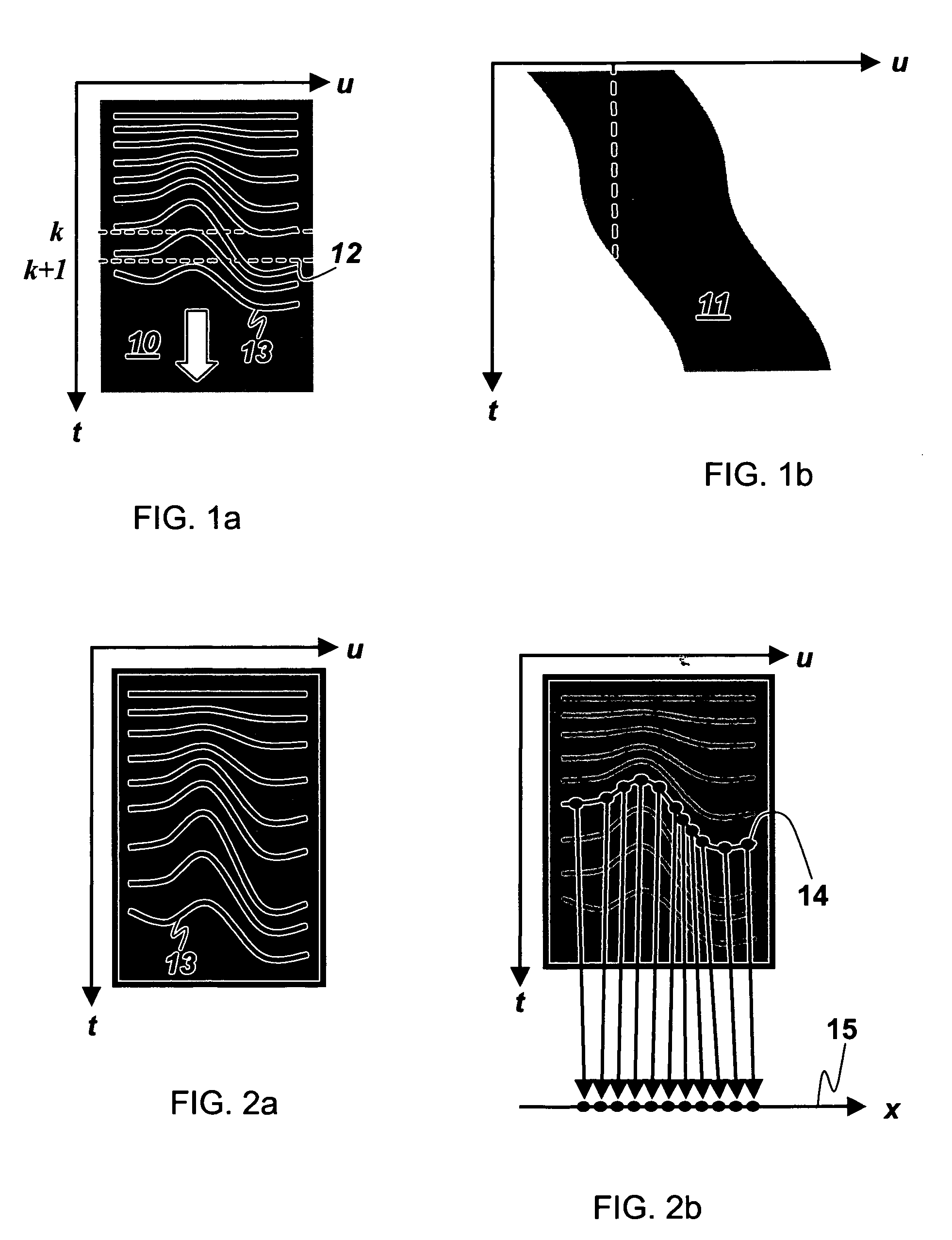
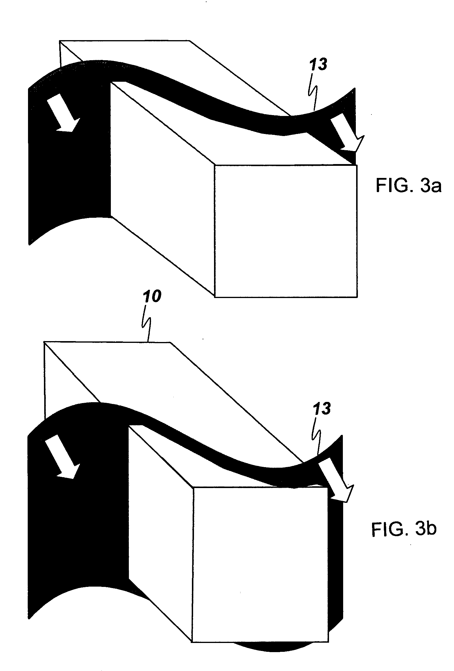
[0097] The invention creates a spatio-temporal video warping framework with which there are associated three conceptual stages: constructing a space-time volume, sweeping the volume with an evolving time front surface, and mapping the resulting time slices to produce the warped output video frames. Before proceeding with a more detailed description of the process, we introduce the notation for the different coordinates systems involved: [0098] 1. Original video coordinates (x,y,t) denote the (x,y) location in input video frame t, where (x, y) are given in the local coordinate system of each frame. [0099] 2. Registered space-time coordinates (u,v,t), denote locations in the space-time volume. Here (u,v) refer to some global coordinate system available after video registration. [0100] 3. Warped video coordinates (x′,y′,t′) denote the (x′,y′) location in the output video frame t′, again, in the local coordinate system of each frame.

1.1. The Spac...


PUM


Abstract

A computer-implemented method and system for transforming a first sequence of video frames of a first dynamic scene captured at regular time intervals to a second sequence of video frames depicting a second dynamic scene wherein for at least two successive frames of the second sequence, there are selected from at least three different frames of the first sequence portions that are spatially contiguous in the first dynamic scene and copied to a corresponding frame of the second sequence so as to maintain their spatial continuity in the first sequence. In a second aspect, for at least one feature in the first dynamic scene respective portions of the first sequence of video frames are sampled at a different rate than surrounding portions of the first sequence of video frames; and the sampled portions are copied to a corresponding frame of the second sequence.

Description

RELATED APPLICATONS [0001] This application claims benefit of provisional applications Ser. No. 60 / 624,896 filed Nov. 5, 2004 and 60 / 664,371 filed Jan. 18, 2005 whose contents are included herein by reference.FIELD OF THE INVENTION [0002] This invention relates to image and video based rendering, where new images and videos are created by combining portions from multiple original images of a scene. PRIOR ART [0003] Prior art references considered to be relevant as a background to the invention are listed below and their contents are incorporated herein by reference. Additional references are mentioned in the above-mentioned U.S. provisional applications Nos. 60 / 624,896 and 60 / 664,371 and their contents are incorporated herein by reference. Acknowledgement of the references herein is not to be inferred as meaning that these are in any way relevant to the patentability of the invention disclosed herein. Each reference is identified by a number enclosed in square brackets and according...

Claims


Application Information

Patent Timeline
Patent Type & Authority Applications(United States)
IPC IPC(8): H04N7/00
CPCG06T3/0087G06T13/80H04N5/2628H04N5/2625G06T2210/44
Inventor PELEG, SHMUELRAV-ACHA, ALEXANDERLISCHINSKI, DANIEL
Owner BRIEFCAM LTD
Why Eureka
Try Eureka