Refrigerator door with end cap

a technology of end caps and refrigerator doors, which is applied in the field of refrigerator doors, can solve the problems of increasing the complexity of the door manufacturing process and the increase of material variations that must be accommodated

Active Publication Date: 2006-11-30
MAYTAG
View PDF39 Cites 102 Cited by
  • Summary
  • Abstract
  • Description
  • Claims
  • Application Information

AI Technical Summary

Problems solved by technology

Such dual bends increases the complexity of the door manufacturing process and increases the material variations which must be accommodated.

Method used


Image

  • Refrigerator door with end cap
  • Refrigerator door with end cap
  • Refrigerator door with end cap

Examples


Embodiment Construction

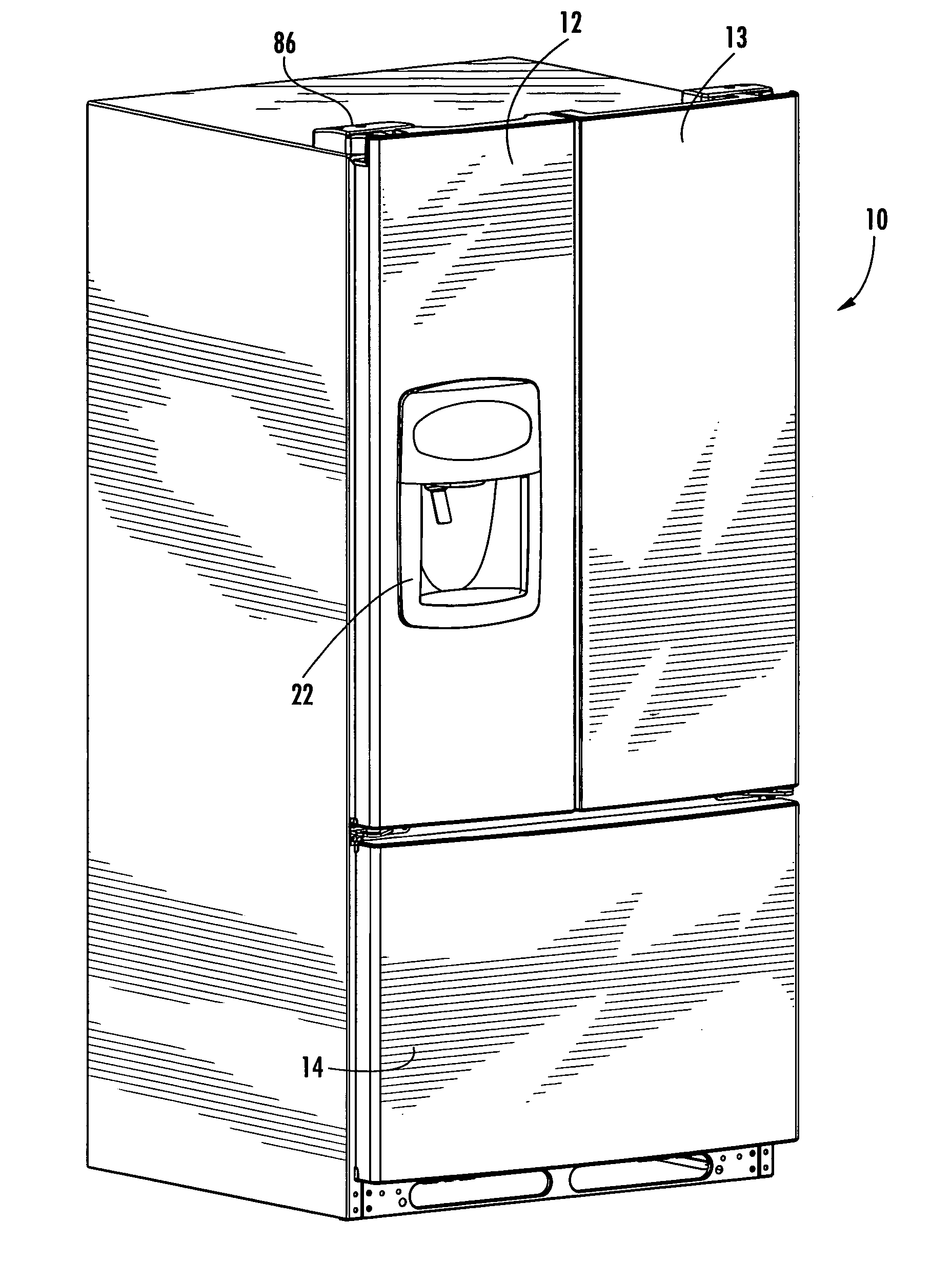
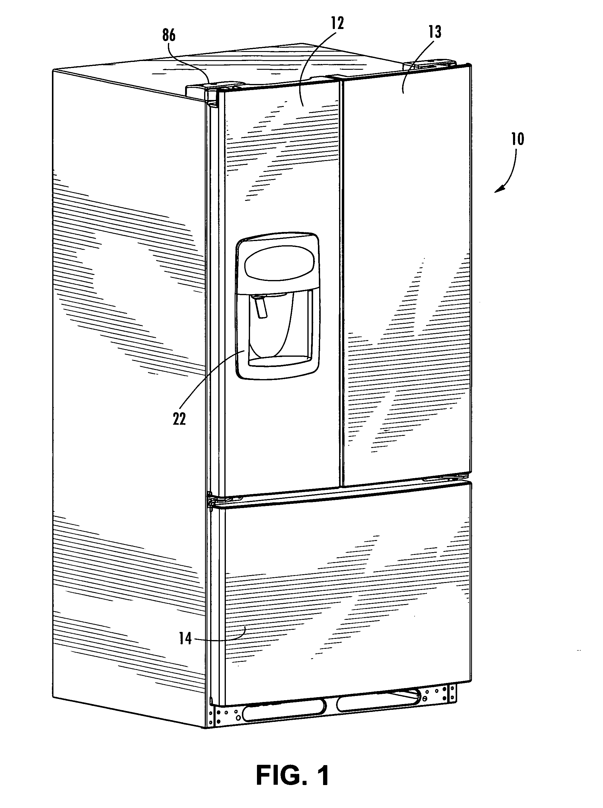
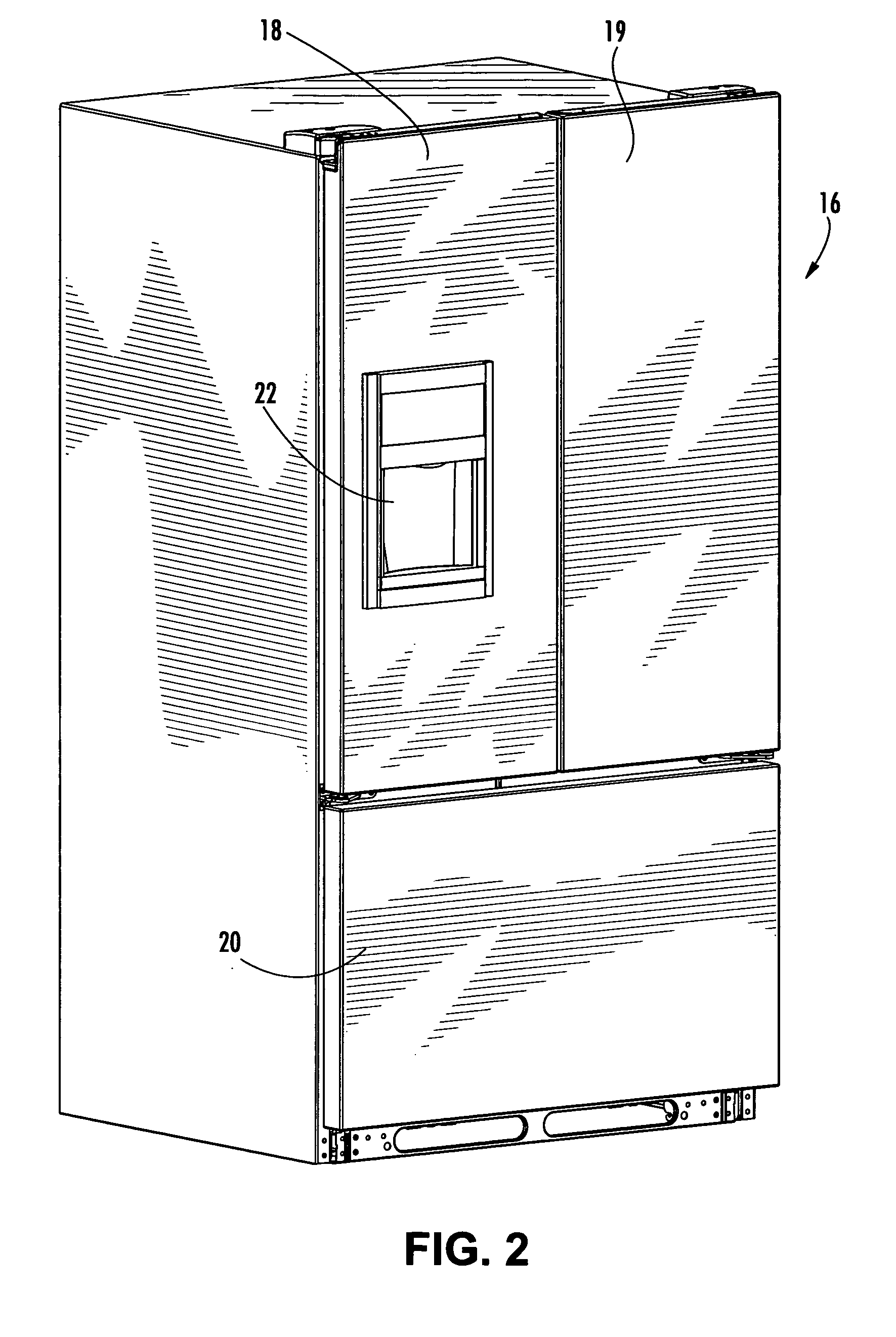
[0040]FIGS. 1 and 2 show two embodiments of a refrigerator having an upper fresh food compartment and a lower freezer compartment. In FIG. 1, the refrigerator 10 includes a pair of French doors 12, 13 for the fresh food compartment and a freezer door 14. The doors 12, 13, 14 are contoured across the width of each door, so that the front of the refrigerator 10 is slightly curved. FIG. 2 shows a refrigerator 16 with French doors 18, 19 for the fresh food compartment and a freezer door 20 for the freezer compartment. The doors 18, 19 and 20 have a flat profile, so that the front of the refrigerator 16 is flat.

[0041]FIGS. 3 and 4 shows the left hand fresh food door 12 of the refrigerator 10. The door 12 includes an ice and water dispenser 22. The structure of the door 12 includes an outer metallic panel 24, an upper end cap 26, a lower end cap 28, and an interior liner 30. It is understood that the right hand door 13 is constructed similarly to the left hand door 12, with the exception...


PUM


Abstract

An improved refrigerator door is provided with a metal outer panel and upper and lower plastic end caps installed on top and bottom edges of the door. The caps include grooves to receive flanges on the edges of the panel, thereby mounting the caps to the panel. The caps include ratcheting members to provide a mating fit with the panel. A bushing is snap fit into the upper cap without the use of hardware fasteners. Electric wires and a water line extend downwardly through the bushing to an ice and water dispenser in the door.

Description

BACKGROUND OF THE INVENTION [0001] Refrigerator doors typically are formed with a metal outer panel and a plastic inner liner, with insulation between the panel and the liner. In the manufacturing process, the outer panel is formed from a flat sheet of metal, with the sequential steps of bending, welding, and painting. It is desirable to buy pre-painted steel, so as to eliminate the costly painting step in the manufacturing process. [0002] The prior art refrigerator door manufacturing process also must accommodate variations in the formation of the outer metal panel. For example, while it is desirable to use the same tooling to manufacture the door panels, stainless steel and cold rolled steel have different bending characteristics, which require different tooling. Typically, the edges of the door panel are bent twice to form an edge at 90 degrees to the body of the panel, and an inwardly extending 90 degree lip, forming a channel between the panel body and the lip. Such dual bends ...

Claims


Application Information

Patent Timeline
Patent Type & Authority Applications(United States)
IPC IPC(8): E06B3/00
CPCF25D2323/021F25D23/02
Inventor LEIMKUEHLER, SCOTT W.MCELVAIN, CHRISROTTER, CHAD J.
Owner MAYTAG
Why Eureka
Try Eureka