

Leveling device
a leveling device and leveling technology, applied in the direction of manufacturing tools, furniture parts, machine supports, etc., can solve the problems of not having the means to threaten up the shaft and against the appliance in order to lock the shaft in position, and needing to employ extraneous tools to achieve the leveling
- Summary
- Abstract
- Description
- Claims
- Application Information
AI Technical Summary
Problems solved by technology
Method used
Image

Examples
Embodiment Construction
[0032] The preferred embodiments depicted in the drawing comprise the improved leveling device for use with an appliance having a threaded receptacle for receiving an elongated adjusting leg. Without departing from the generality of the invention disclosed herein and without limiting the scope of the invention, the discussion that follows, will refer to the invention as depicted in the drawing. The term appliance is meant to encompass various types of equipment and apparatus, such as but not limited to large commercial and residential appliances, office furniture, business machines, manufacturing and communication machines and equipment, display and storage equipment, and the like.
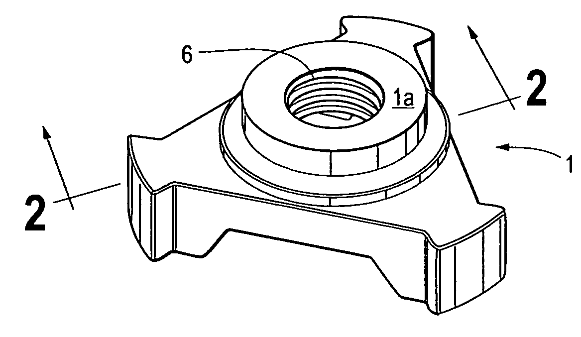
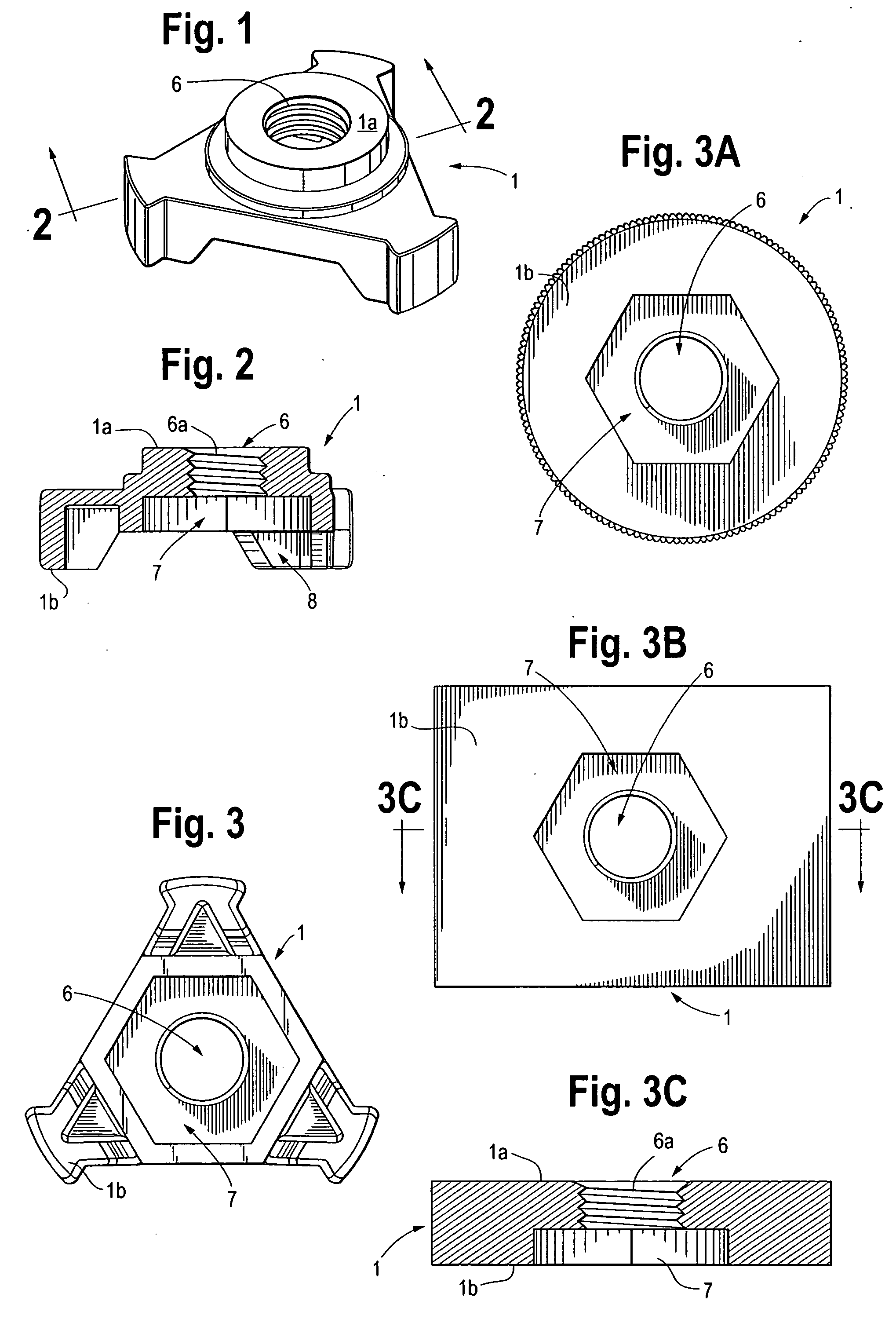
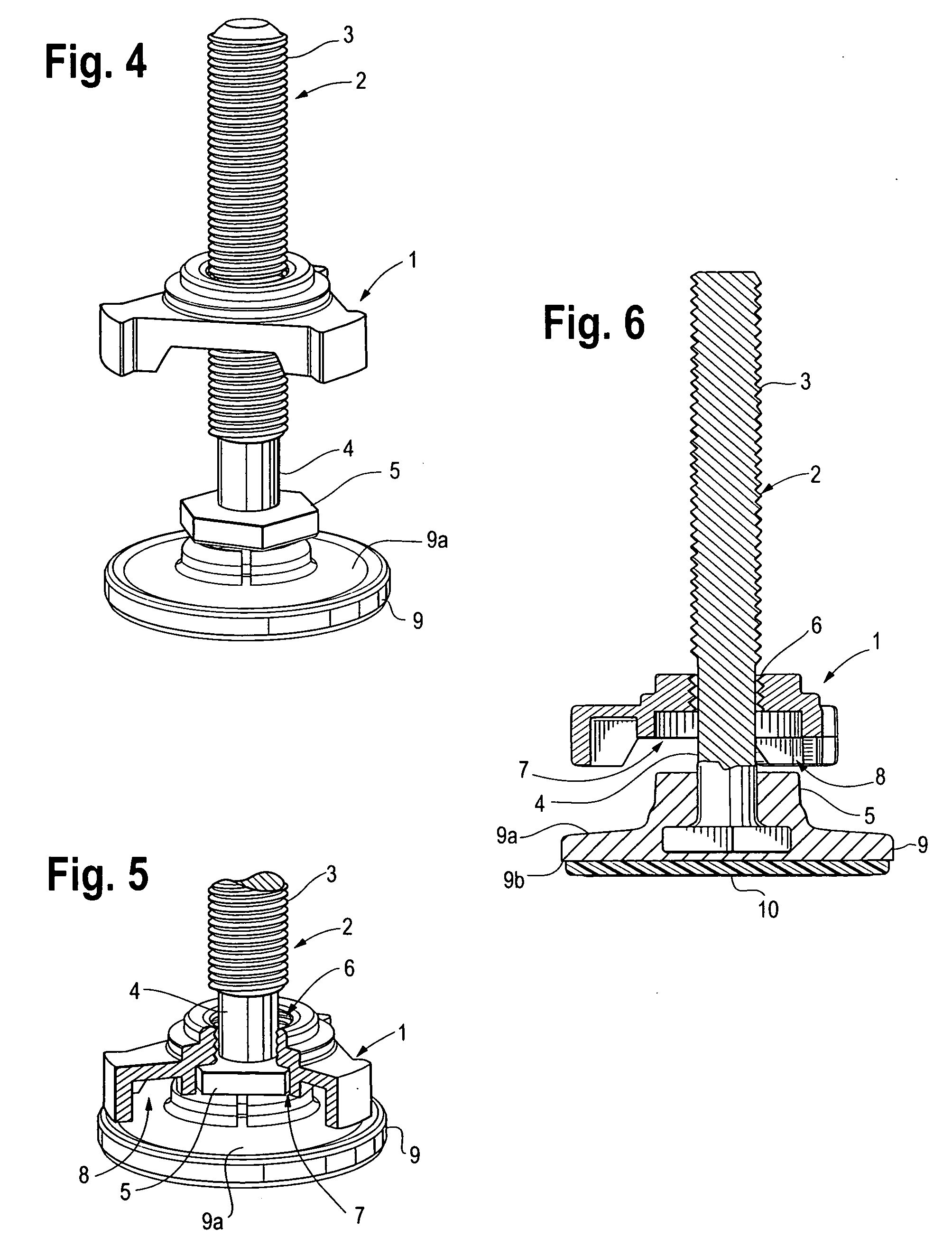
[0033] An improved leveling device for use with an appliance having a threaded receptacle for receiving an elongated adjusting leg, wherein the improvement comprises the elongated adjusting leg 2 having an upper longitudinal threaded section 3 adapted for engaging the threaded receptacle 18, an intermedia...
PUM
 Abstract
Description
Claims
Application Information