Hydraulic pump unit

Inactive Publication Date: 2006-12-07
KANZAKI KOKYUKOKI MFG
View PDF4 Cites 19 Cited by
  • Summary
  • Abstract
  • Description
  • Claims
  • Application Information

AI Technical Summary

Benefits of technology

[0017] With this configuration, the manual operation power and the manual operation amount required for operating the capacity adjusti

Problems solved by technology

However, in the conventional hydraulic pump unit of variable displacement type, since the capacity adjusting mechanism is merely connected to a manual controlling member such as a traveling lever erected from right and left side floors of a driver sheet via a machinery link mechanism, large manual operation power and manual operation amount are required for the travel operation of a vehicle.
Since the large manual operation power and the manual operation amount are required

Method used


Image

  • Hydraulic pump unit
  • Hydraulic pump unit
  • Hydraulic pump unit

Examples


embodiment 1

[0046] Hereinafter, a preferred embodiment of a hydraulic pump unit according to the present invention will be described referring to the accompanying drawings.

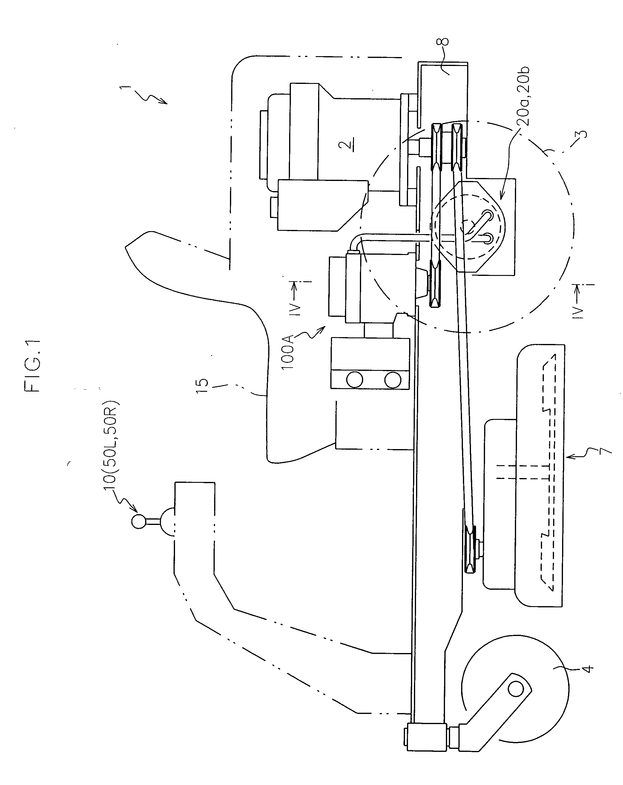
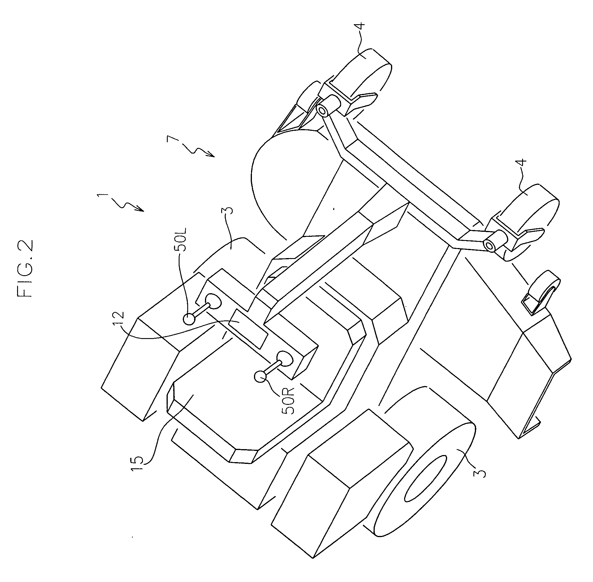
[0047]FIGS. 1 and 2 show a schematic side view and a schematic perspective view of a working vehicle 1 to which a hydraulic pump unit 100A according to the present embodiment is applied, respectively.

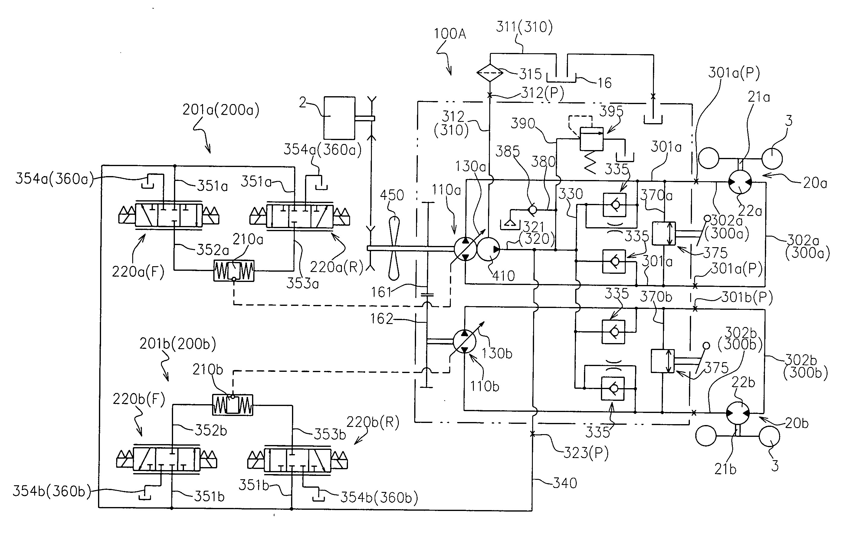
[0048]FIG. 3 shows a hydraulic circuit diagram of the working vehicle 1.

[0049] As shown in FIGS. 1 to 3, the working vehicle 1 is provided with a vehicle frame 8, a driving source 2 supported by the vehicle frame 8, a pair of right and left driving wheels 3 (rear wheels in the present embodiment), caster wheels 4 (a pair of front wheels in the present embodiment), first and second hydraulic motor units 20a, 20b for respectively and independently driving the pair of driving wheels 3, a hydraulic pump unit 100A of variable displacement type according to the present embodiment, and a travel operation mechanism 10 for changing the...

embodiment 2

[0168] Hereinafter, another embodiment of the hydraulic pump unit according to the present invention will be described referring to the accompanying drawings.

[0169]FIG. 11 shows a sectional view taken in a line orthogonal to pump shafts of a hydraulic pump unit 100B according to the present embodiment.

[0170] As shown in FIG. 11, the hydraulic pump unit 100B according to the present embodiment is different from the hydraulic pump unit 100A mainly in that the piston accommodating chamber is provided in a wall portion of a pump case.

[0171] Therefore, the same members as the embodiment 1 in the figures are designated by the same numerals, and the detailed description thereof are omitted.

[0172] Specifically, the hydraulic pump unit 100B according to the present embodiment has a case body 170B instead of the case body 170 in the hydraulic pump unit 100A.

[0173] As shown in FIG. 11, the case body 170B is constituted so that the peripheral wall defines the first and second piston accomm...

embodiment 3

[0177] Hereinafter, still another embodiment of the hydraulic pump unit according to the present invention will be described referring to the accompanying drawings.

[0178]FIG. 12 shows a longitudinal sectional view taken in a line along pump shafts of the hydraulic pump unit 100C according to the present embodiment.

[0179] The same members as those of the embodiment 1 or 2 are designated by the same numerals, and the detailed description thereof are omitted.

[0180] As shown in FIG. 12, the hydraulic pump unit 100C according to the present embodiment is provided with pump cases which respectively correspond to the first and second hydraulic pump bodies 110a, 110b.

[0181] That is, the hydraulic pump unit 100C is provided with a pair of pump cases 120C for respectively accommodating the first hydraulic pump body 110a and the second hydraulic pump body 110b. The pair of pump cases 120C are arranged in parallel.

[0182] The hydraulic pump unit 100C may be provided with a pair of pulleys 1...


PUM


Abstract

There is provided a hydraulic pump unit of variable displacement type disposed away from a pair of hydraulic motor units which are capable of being independently arranged, the pump unit fluid-connected to the pair of hydraulic motor units so as to change the outputs of the pair of hydraulic motor units in both forward and reverse rotation directions. The pump unit includes a hydraulic pump body operatively rotated and driven by a driving source, a pump case surrounding the hydraulic pump body, a capacity adjusting mechanism for changing the capacity of the hydraulic pump body, and an actuator for operating the capacity adjusting mechanism. The actuator is controlled based on a manual operation signal corresponding to a manual operation amount.

Description

BACKGROUND OF THE INVENTION [0001] 1. Field of the Invention [0002] The present invention relates to a hydraulic pump unit of variable displacement type disposed away from a pair of hydraulic motor units which are capable of being independently arranged, the hydraulic pump unit fluid-connected to the pair of hydraulic motor units so as to change the outputs of the pair of hydraulic motor units in both forward and reverse directions. [0003] 2. Related Art [0004] It has been conventionally known that a hydraulic pump unit of variable displacement type and a hydraulic motor unit, which are fluid-connected to each other so as to form an HST, are configured to be capable of being independently arranged. [0005] The hydraulic pump unit and the hydraulic motor unit are particularly useful in a working vehicle needing to provide a space between a pair of driving wheels so as to stabilize the body posture at the time of turning such as a mower tractor capable of turning in place (zero turn) (...

Claims


Application Information

Patent Timeline
IPC IPC(8): F01B13/04
CPCB60Y2200/223F04B1/22F04B1/26F04B1/324F16H61/437F04B23/06F16H39/14F16H61/4052F16H61/42F04B17/05
Inventor OHASHI, RYOTA
Owner KANZAKI KOKYUKOKI MFG
Why Eureka
Try Eureka