Linked mode for a multi-axis machine control

a multi-axis machine control and linked mode technology, applied in the direction of applications, instruments, ways, etc., can solve the problems of time and distraction, additional operator oversight, and additional complexity of the control system, so as to facilitate signal communication, facilitate user operation, and promote consistent, accurate apparatus setup

Active Publication Date: 2005-09-08
CATERPILLAR TRIMBLE CONTROL TECH
View PDF13 Cites 13 Cited by
  • Summary
  • Abstract
  • Description
  • Claims
  • Application Information

AI Technical Summary

Benefits of technology

[0007] In the present context, the term “substantially” refers to an arrangement of elements or features that, while in theory would be expected to exhibit exact correspondence or behavior, may, in practice embody something less than exact. As such, the term denotes the degree by which a quantitative value, measurement or other related representation may vary from a stated reference without resulting in a change in the basic function of the 
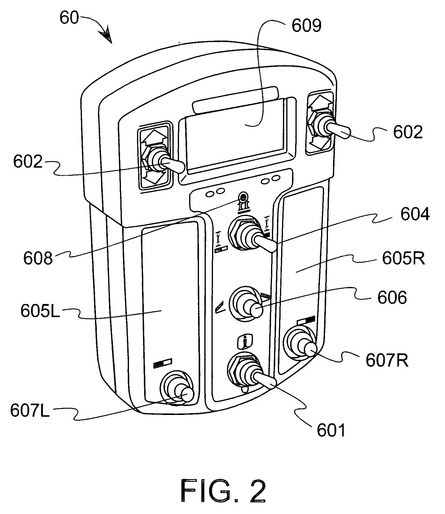
subject matter at issue. The controller includes at least one user-operable input mechanism to facilitate manual actuator operation and an information processor to facilitate the automatic operation of the actuators. The device also includes an output configured to display information pertaining to a position of the blade, such as its elevation. Optionally, the output is configured to display a single blade position value. The 
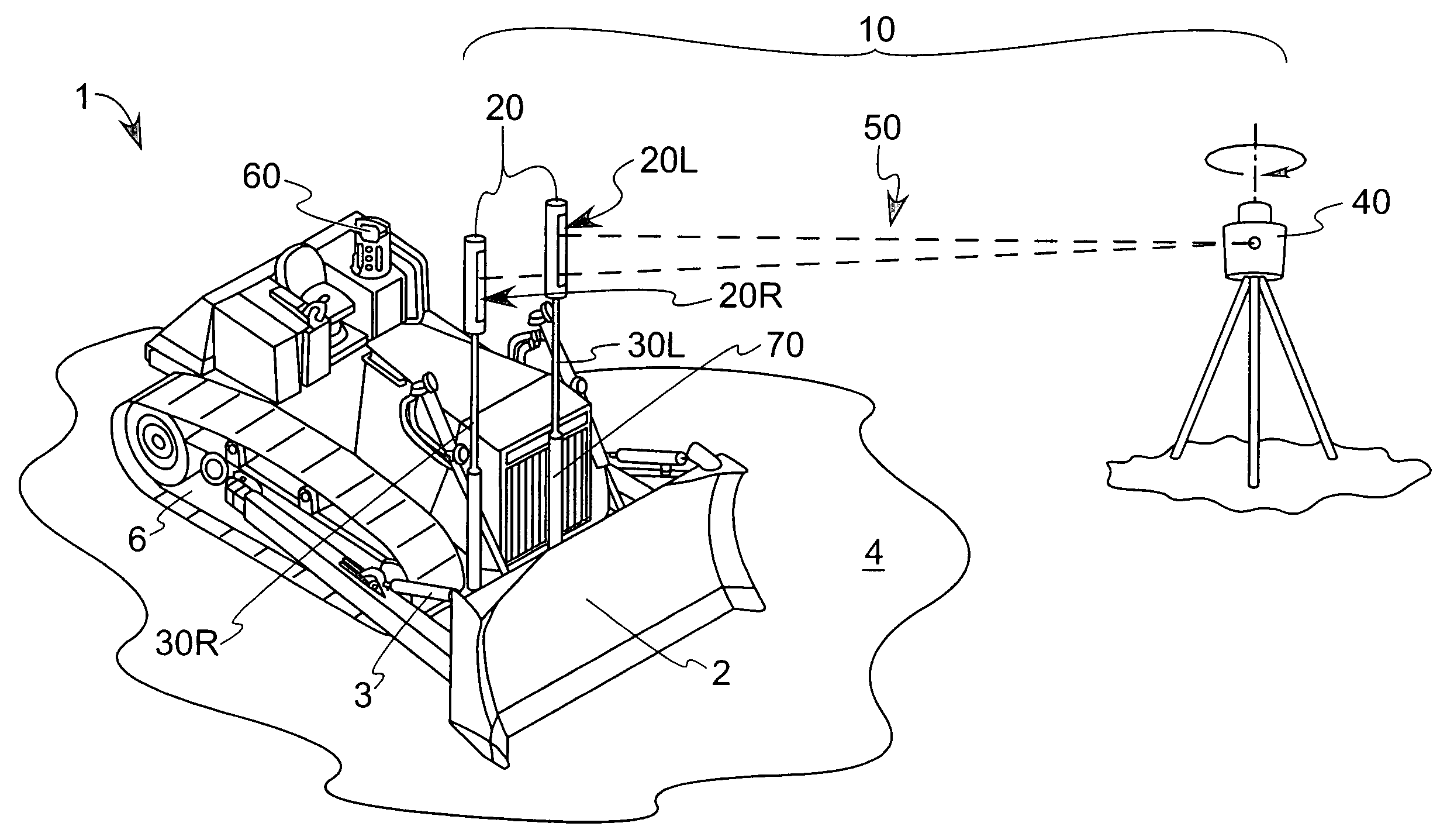
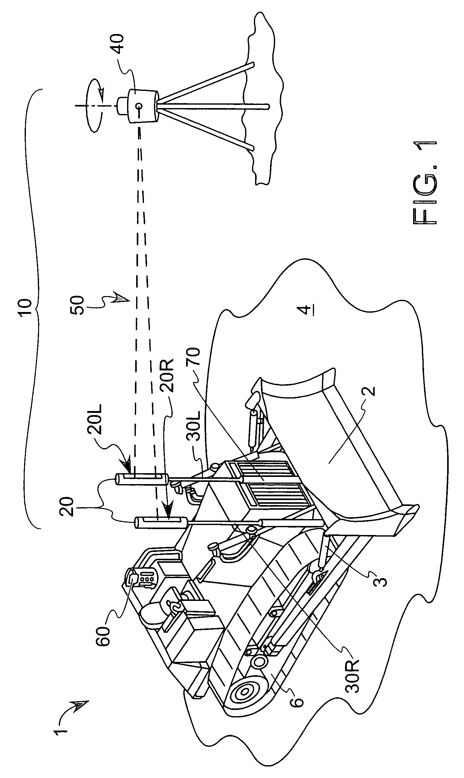
system may further include a laser guidance apparatus with a signal source configured to provide a reference signal to the controller and a plurality of detectors configured to be in signal communication with the source and the controller. This allows that in either manual or automatic operation, the actuators can move the blade in response to a difference between the detected reference signal and the blade position.
[0008] According to another aspect of the present invention, a control system for a machine tool includes a plurality of actuators configured to move the tool, and a guidance apparatus configured to control the actuators. The guidance apparatus includes a signal source, a plurality of detectors configured to be signally coupled to the source, and a controller configured to operate in more than one operational mode. In the present context, the detectors and source are considered to be signally coupled to one another as long as the signal emanating from the source is sensed by the signal-sensing portion of the detector. The detectors are connected to the machine tool, either at opposing ends, one at the end with one at the center, or in any other spaced relationship across the tool, depending on the tool configuration. The controller is made up of at least a data interface coupled to the detectors, at least one user-operable input mechanism, an information processor responsive to the input mechanism and an output configured to display information in either of the plurality of operational modes. When the controller is in a first of the plurality of operational modes, each of the actuators is driven by the controller independently of the other actuators. When in a second operational mode, the plurality of actuators are responsively linked such that they are driven in unison with one another. This is beneficial in that even when at least one of the detectors is no longer signally coupled to the source, the relative position between the ends (or end and center) of the tool remain fixed, thereby avoiding erroneous tool settings. An additional benefit arises in that an operator need only refer to a single tool position displayed on the output when adjustments to the tool position are necessary.
[0014] Optionally, a mast is coupled to each of the detectors and configured to move the detectors to facilitate signal communication between the detector and the signal source. By way of example, the masts can be movable, and also include motors to translate the corresponding detectors. As previously discussed, in a linked mode of operation, movement of particular components (such as blade actuators, or masts to move the detectors, for example) are responsively linked such that they are driven in unison with one another. By requiring only one control point to be input during the benching process, the linked mode simplifies user operation and promotes consistent, accurate apparatus setup. The method includes the steps of providing a benchmark at a location accessible to the blade, positioning the blade substantially on the benchmark, transmitting a signal with the source, inputting instructions into the input mechanism and receiving the signal with at least one of the detectors until a setpoint is established by at least one of the detectors. In configurations where masts are employed, the detectors can be moved until at least one of them is substantially aligned with the signal to define a substantially on-grade position. In the linked mode of operation, the masts can extend or retract in response to operator input (such as an offset command). Upon receipt of the command, the masts move the detectors until the detectors comply with the input command. In another option, it is the portion of the blade that is substantially underneath one of the detectors that is positioned substantially on the benchmark. As previously described, this portion of the blade corresponds to a particular location that coincides with the placement of the masts and detectors above it, including the blade center, right side or left side. In linked mode, the user inputs are simplified; for example, the inputting of instructions can be something very simple, such as pushing a button to initiate a search for the transmitted signal by at least one of the detectors. This also simplifies output that the user has to consider, where (by way of example) a single reference elevation corresponding to the setpoint (i.e., on-grade) position can be displayed on the output. In this context, the terms “reference elevation” and “setpoint” can be used interchangeably to describe the on-grade position of the detectors to the signal source.

Problems solved by technology

While the independent mode of control of a single blade (or the control of two blades in the case of a tandem-blade device) of the dual elevation machine control system gives the operator significant flexibility, such as enhanced levels of blade adjustability and concomitant earth grading ability, it also introduces additional complexity into the control system, necessitating additional operator oversight.
This is undesirable, requiring the operator to concentrate on monitoring two blade values on the display screen, and inputting two offset values into the controller, thereby necessitating additional input, time and distraction from other operational tasks, even in the majority of operating situations where only a single blade position is being varied.

Method used


Image

  • Linked mode for a multi-axis machine control
  • Linked mode for a multi-axis machine control
  • Linked mode for a multi-axis machine control

Examples


Embodiment Construction

[0022]FIG. 1 shows an earth-grading machine 1 according to an aspect of the present invention, including a dual laser elevation machine control system 10 used to establish grade and to maintain elevation control for a contouring blade 2 mounted to the machine 1. While shown in its present configuration for use with construction earth-grading machinery 1, control system 10 can also be used on with agricultural equipment as well. The control system 10 includes detectors 20 that are mounted to the machine 1 through optional masts 30. It will be understood that subsequent discussion of detectors and their corresponding masts in the general sense will include reference numbers 20 and 30, respectively, and that the references to a left and right detector 20L, 20R and a left and right mast 30L, 30R are made manifest from the drawing. Masts 30L, 30R, which may include telescoping features 70, can be either manually, hydraulically or electrically adjusted, the latter two cooperative with a m...


PUM


Abstract

A tool control system includes actuators to move the tool, a controller to permit either manual or automatic tool operation, and an output configured to display information pertaining to a position of the tool. In addition, the tool can be moved in either an independent or linked mode, the latter such that during tool operation, both sides of the tool can move substantially in unison with one another, or during system setup, detectors used to ensure coordination with of the tool to a known benchmark can move substantially in unison with one another. The controller can display either single or multiple numbers related to the tool position, and can accept either single or multiple user inputs to move the tool by a user-determined or system-determined amount.

Description

BACKGROUND OF THE INVENTION [0001] The present invention relates generally to a simplified machine control device, and more particularly to a device that reduces the complexity of the user interface for controlling blade position in earth-grading machinery. [0002] In construction and related earth-moving job sites, an on-site elevation positioning or guidance system can be used in conjunction with earth-grading machinery, such as bulldozers and earthmovers, to provide information about, or control blade lift (also known as grade or elevation) and tilt (also known as slope or side-to-side angle) of, the blade relative to the ground being graded in order to cut and fill earth in accordance with a predetermined grading plan. In “indicate-only” systems, guidance information is provided, whereas in automated systems, the information derived from the differences between the current and desired blade positions can additionally be used to drive the blade to a preferred position. Detectors m...

Claims


Application Information

Patent Timeline
Patent Type & Authority Applications(United States)
IPC IPC(8): A01B63/111
CPCA01B69/008E01C19/006Y10S37/907E02F3/847E01C23/08
Inventor WRAY, ALBERT A.
Owner CATERPILLAR TRIMBLE CONTROL TECH
Why Eureka
Try Eureka