
Screw compressor capable of manually adjusting both internal volume ratio and capacity and combined screw compressor unit accommodating variation in suction or discharge pressure

Inactive Publication Date: 2007-01-23
MAYEKAWA MFG CO LTD
View PDF6 Cites 13 Cited by
  • Summary
  • Abstract
  • Description
  • Claims
  • Application Information

AI Technical Summary

Benefits of technology

[0025]An object of the present invention is to provide a screw compressor of simple structure and low cost equipped with slide valves for adjusting internal volume ratio and capacity (the flow rate of discharge gas) without the need of providing an electric power source, the screw compressor being composed such that the sliding and securing in place of the internal volume ratio adjusting slide valve and the sliding of the capacity adjusting slide valve can be operated manually.
[0026]Another object of the present invention is to provide a combined compressor unit for achieving high compression ratio with superior efficiency, which can accommodate the variation in suction and discharge pressure.

Problems solved by technology

Such a compressor can be used for a variety of uses, however, the construction is complicated, which causes increase in cost.
Therefore, there is inconvenience that such a compressor can not be used as it is in wild land where electricity can not be available.
For example, in natural gas fields, screw compressors are driven by gas engines using extracted natural gas as fuel, and it is troublesome in many cases to provide a electric power source for adjusting internal volume ratio and capacity of the screw compressors.
There have been developed screw compressors capable of adjusting internal volume ratio and capacity, however, they are inevitably complicated in structure and high in cost as mentioned above.
Therefore, the gas discharged from the lower pressure compressor expands in the space between the lower pressure compressor and higher pressure compressor, that means that the lower pressure compressor compresses the gas excessively high and does wasteful compression work, resulting in decreased efficiency of the lower pressure compressor.
Now if we call the ratio (the volume of the enclosed space between teeth of the lower pressure compressor when discharge begins) / (the volume of the enclosed space between teeth of the higher pressure compressor when compression begins) as displacement ratio, the smaller the displacement ratio is, the lower the intermediate pressure becomes, resulting in excessively high compression in the lower pressure compressor.
As described above, when the suction pressure of the lower pressure compressor increases, the discharge pressure of the higher pressure compressor increases considerably, and there happens the case that the discharge pressure exceeds the limit pressure permissible for the higher pressure compressor, which may induce damage of the components of the higher pressure compressor.

Method used


Image

  • Screw compressor capable of manually adjusting both internal volume ratio and capacity and combined screw compressor unit accommodating variation in suction or discharge pressure
  • Screw compressor capable of manually adjusting both internal volume ratio and capacity and combined screw compressor unit accommodating variation in suction or discharge pressure
  • Screw compressor capable of manually adjusting both internal volume ratio and capacity and combined screw compressor unit accommodating variation in suction or discharge pressure

Examples


Embodiment Construction

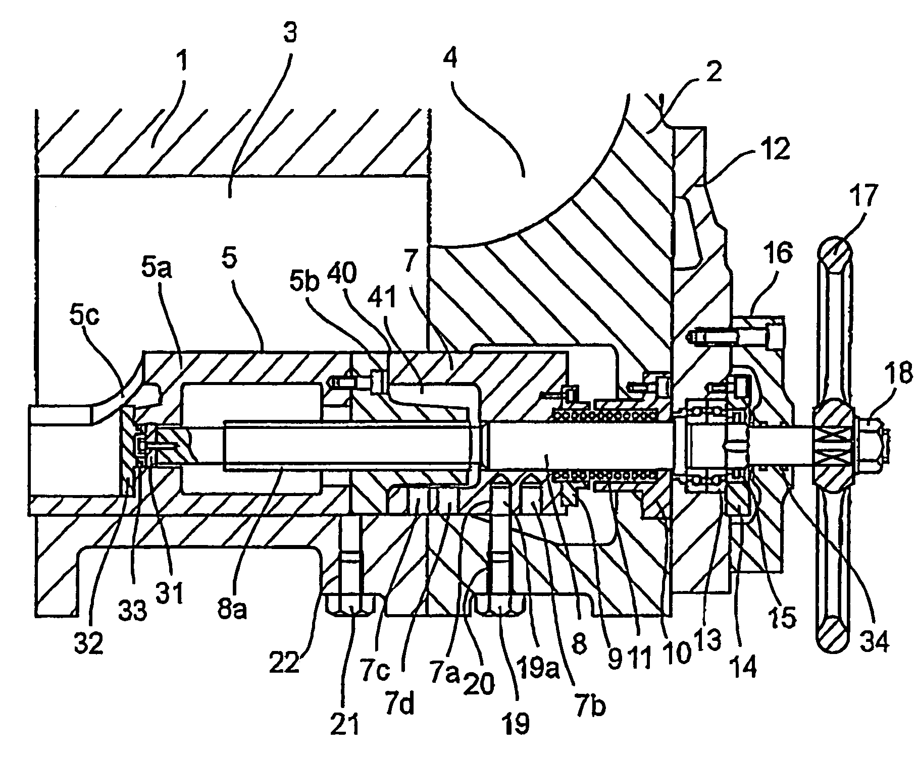
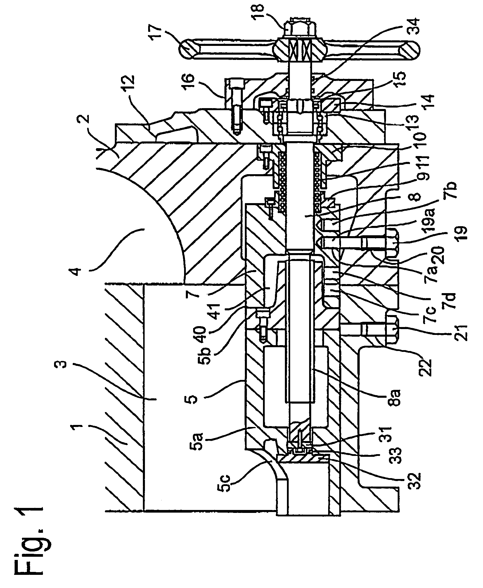
[0046]A preferred embodiment of the present invention will now be detailed with reference to the accompanying drawings. It is intended, however, that unless particularly specified, dimensions, materials, relative positions and so forth of the constituent parts in the embodiments shall be interpreted as illustrative only not as limitative of the scope of the present invention.

[0047]FIG. 1 is a longitudinal sectional view showing the structure of the part where the internal volume adjusting slide valve and capacity adjusting slide valve are mounted of the screw compressor according to the present invention. Referring to FIG. 1, reference numeral 1 is a rotor casing, 2 is a suction side bearing housing, 3 is the rotor chamber in the rotor casing 1 in which a male and female rotors (not shown in the drawing) meshing with each other are accommodated, the rotors being supported by bearings in a suction side bearing housing and a discharge side bearing housing not shown in the drawing. Ref...


PUM


Abstract

A screw compressor is equipped with a manually operated internal volume ratio adjusting slide valve and capacity adjusting slide valve. The compressor is simple in construction, can be produced with low cost, can accommodate decrease in suction pressure, for example, in an aged gas well, and can be operated without an electric power source for controlling the operation thereof. Also a combined screw compressor unit consisting of a plurality of screw compressors for producing high discharge pressure is provided which can accommodate high suction pressure in order not to overload the higher pressure compressor or compressors with the efficiency of the unit kept as high as possible by including at least a screw compressor according to the present invention in the unit.

Description

CROSS-REFERENCE TO RELATED APPLICATION[0001]This is a continuation-in-part application of U.S. Ser. No. 10 / 386,112 filed on Mar. 12, 2003.BACKGROUND OF THE INVENTION[0002]1. Field of the Invention[0003]The present invention is related to a screw compressor capable of manually adjusting internal volume ratio and capacity (the flow rate of discharge gas) thereof and a combined screw compressor unit suitable for application in the case the suction pressure or discharge pressure varies widely when used for compressing and supplying gas for a refrigerating machine, air conditioner, gas turbine booster, natural gas pipe line, chemical process, spherical holder, etc.[0004]2. Description of the Related Art[0005]A screw compressor equipped with a slide valve for adjusting internal volume ratio and an unloader valve for varying the volume of gas to be sucked, is widely used as a low-noise, low-vibration, relatively low-priced compressor which can be adjusted of the compression ratio and flow ...

Claims


Application Information

Patent Timeline
IPC IPC(8): F04B43/12F04B49/00F04C28/12
CPCF04C28/12
Inventor HATTORI, TOSHIROTAKAHASHI, KATSUYUKITANAKA, KIYOSHIMATSUI, AKIRAKOBAYASHI, YOSHIYUKISATO, HARUMI
Owner MAYEKAWA MFG CO LTD
Learn More