Scroll compressor

a compressor and scroll technology, applied in the direction of machines/engines, liquid fuel engines, rotary/oscillating piston combinations for elastic fluids, etc., can solve the problems of increased surface pressure of the localized contact portion and damage to the scroll, and achieve the effect of suppressing the occurrence of localized contact, and reducing the volumetric efficiency

Active Publication Date: 2022-06-09
SANDEN CORP
View PDF2 Cites 0 Cited by
  • Summary
  • Abstract
  • Description
  • Claims
  • Application Information

AI Technical Summary

Benefits of technology

[0015]According to the present invention, in a scroll compressor which includes a compression mechanism having a fixed scroll and a movable scroll respectively formed on surfaces of mirror plates with spiral laps facing each other, and in which the movable scroll is revolved and turned with respect to the fixed scroll to move a compression chamber formed between the laps of both scrolls from the outside to the inside while reducing the compression chamber thereby to compress a working fluid, the laps of the fixed scroll and the movable scroll are configured to have a plurality of step portions between a winding end portion at an outermost periphery and a winding start portion at an innermost periphery and decrease stepwise in height toward the winding start portion from the winding end portion, and the position and height of each step portion are set so that a base point of each step portion is placed on a predetermined arc drawn on a predetermined plane when the spiral laps are expanded on the predetermined plane. It is therefore possible to set the height of the lap of each scroll to a form close to an actual shape of each scroll of a state of being worn by localized contact due to the influence of a compressive reaction force and thermal expansion, i.e., a familiarized state. Consequently, the occurrence of the localized contact can be effectively suppressed, and a so-called break-in time until volumetric efficiency is saturated can be significantly shortened.
[0016]In particular, as in the invention of claim 2, each step portion is set to a concentric arc shape. More preferably, as in the invention of claim 3, each step portion is set to an arc shape concentric with a base circle of a spiral of each lap or the mirror plate. Consequently, the height of the lap of each scroll can be made to even more accurately correspond to an actual wear shape of the scroll, and the occurrence of the localized contact can be suppressed even more effectively.
[0017]Further, as in the invention of claim 3, the outermost step portion is located 180 deg or more inside from the winding end portion, more preferably, 270 deg inside from the winding end portion as in the invention of claim 4. Consequently, the stability at the time that each scroll is placed with the lap facing down is improved, and the standard at time of setting the height of the lap also becomes easy to be taken.

Problems solved by technology

However, when the operation is performed under high load conditions in a wear-free state at the start of the operation (a state before it has become familiar), there is a high risk that the surface pressure of the localized contact portion will increase and the scroll will be damaged.

Method used


Image

  • Scroll compressor
  • Scroll compressor
  • Scroll compressor

Examples


Embodiment Construction

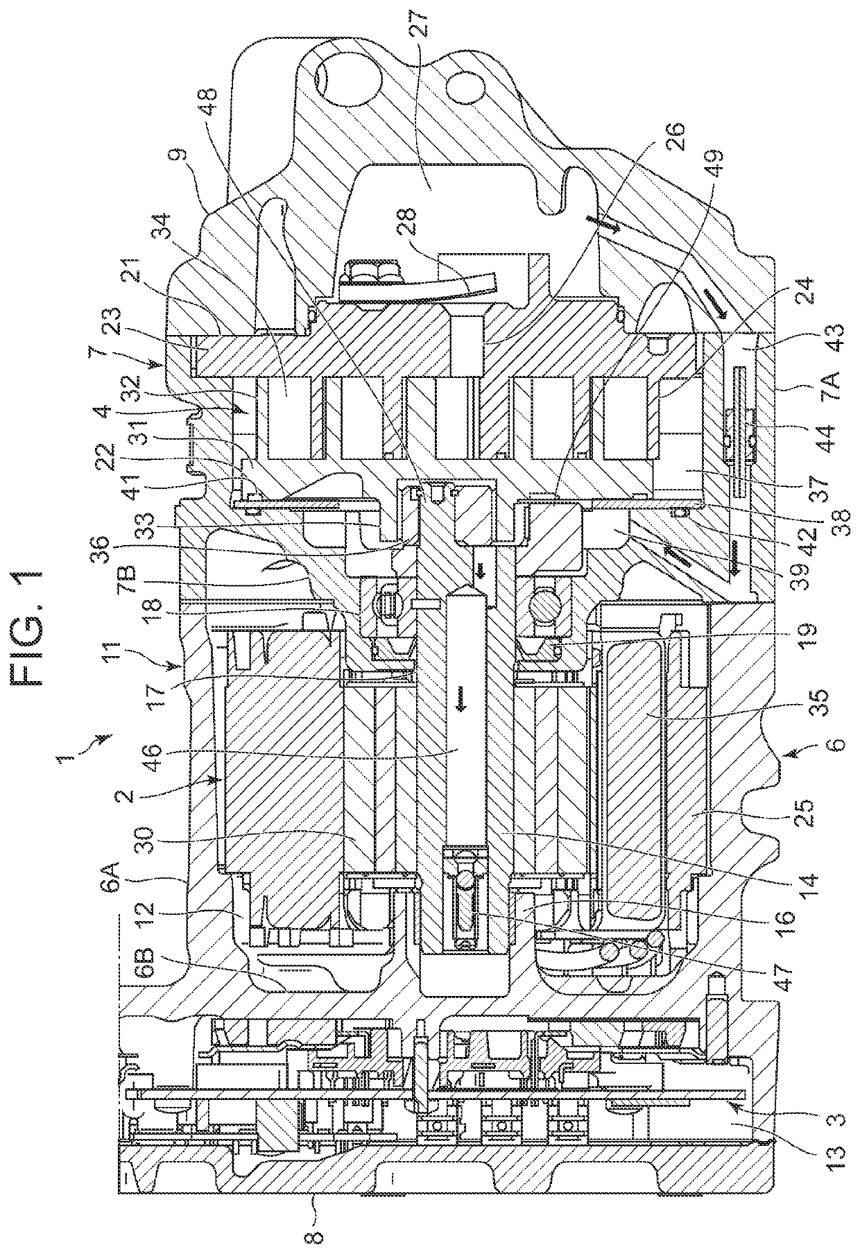
[0024]Hereinafter, an embodiment of the present invention will be described in detail with reference to the drawings. FIG. 1 is a cross-sectional view of a scroll compressor 1 of an embodiment to which the present invention is applied. The scroll compressor 1 of the embodiment is, for example, a so-called inverter-integrated scroll compressor which is used in a refrigerant circuit of a vehicle air conditioning device, sucks a carbon dioxide refrigerant as a working fluid of the vehicle air conditioning device, and compresses and discharges it, and which includes an electric motor 2, an inverter 3 for operating the electric motor 2, and a compression mechanism 4 driven by the electric motor 2.

[0025]The scroll compressor 1 of the embodiment includes a main housing 6 which accommodates the electric motor 2 and the inverter 3 thereinside, a compression mechanism housing 7 which accommodates the compression mechanism 4 thereinside, an inverter cover 8, and a compression mechanism cover 9...


PUM


Abstract

[Problem] A scroll compressor is provided which effectively suppresses the occurrence of localized contact caused by deformation of a fixed scroll or a movable scroll due to the influence of a compressive reaction force or thermal expansion and shortens a break-in time. [Solution] Laps 24 and 32 of a fixed scroll 21 and a movable scroll 22 are constituted to have a plurality of step portions between a winding end portion at an outermost periphery and a winding start portion at an innermost periphery and decrease stepwise in height toward the winding start portion from the winding end portion. The position and height of each step portion are set so that when the spiral laps 24 and 32 are expanded on a predetermined plane, a base point of each step portion is placed on a predetermined arc drawn on the plane.

Description

TECHNICAL FIELD[0001]The present invention relates to a scroll compressor which compresses a working fluid in a compression chamber formed between laps of both a fixed scroll and a movable scroll by revolving and turning the movable scroll with respect to the fixed scroll.BACKGROUND ART[0002]This type of scroll compressor conventionally includes a compression mechanism constituted of a fixed scroll having a spiral lap on the surface of a mirror plate and a movable scroll having a spiral lap on the surface of a mirror plate and is configured in such a manner that a compression chamber is formed between the laps of the respective scrolls with the laps facing each other, and the movable scroll is revolved and turned with respect to the fixed scroll by a motor to thereby move the volume of the compression chamber from the outside to the inside while reducing it, so that a working fluid (refrigerant) is compressed.[0003]In this case, in each scroll, the innermost periphery (central part)...

Claims


Application Information

Patent Timeline
Patent Type & Authority Applications(United States)
IPC IPC(8): F04C18/02
CPCF04C18/0215F04C18/0276F04C23/008
Inventor INABA, HIRONOBUSATO, TAIZOIMAI, TETSUYA
Owner SANDEN CORP
Why Eureka
Try Eureka