Multiple valve device

Active Publication Date: 2015-04-23
HITACHI CONSTR MASCH CO LTD
View PDF9 Cites 17 Cited by
  • Summary
  • Abstract
  • Description
  • Claims
  • Application Information

AI Technical Summary

Benefits of technology

[0019]As a result, the first hydraulic pump is connected to the first pump port provided on the first housing block, and the second hydraulic pump is connected to the second pump port provided on the second housing block. In this case, one relief valve can

Problems solved by technology

Incidentally, in the above-described prior arts, when two or more hydraulic pumps are used as a hydraulic source and a maximum pressure in a hy

Method used


Image

  • Multiple valve device
  • Multiple valve device
  • Multiple valve device

Examples


Embodiment Construction

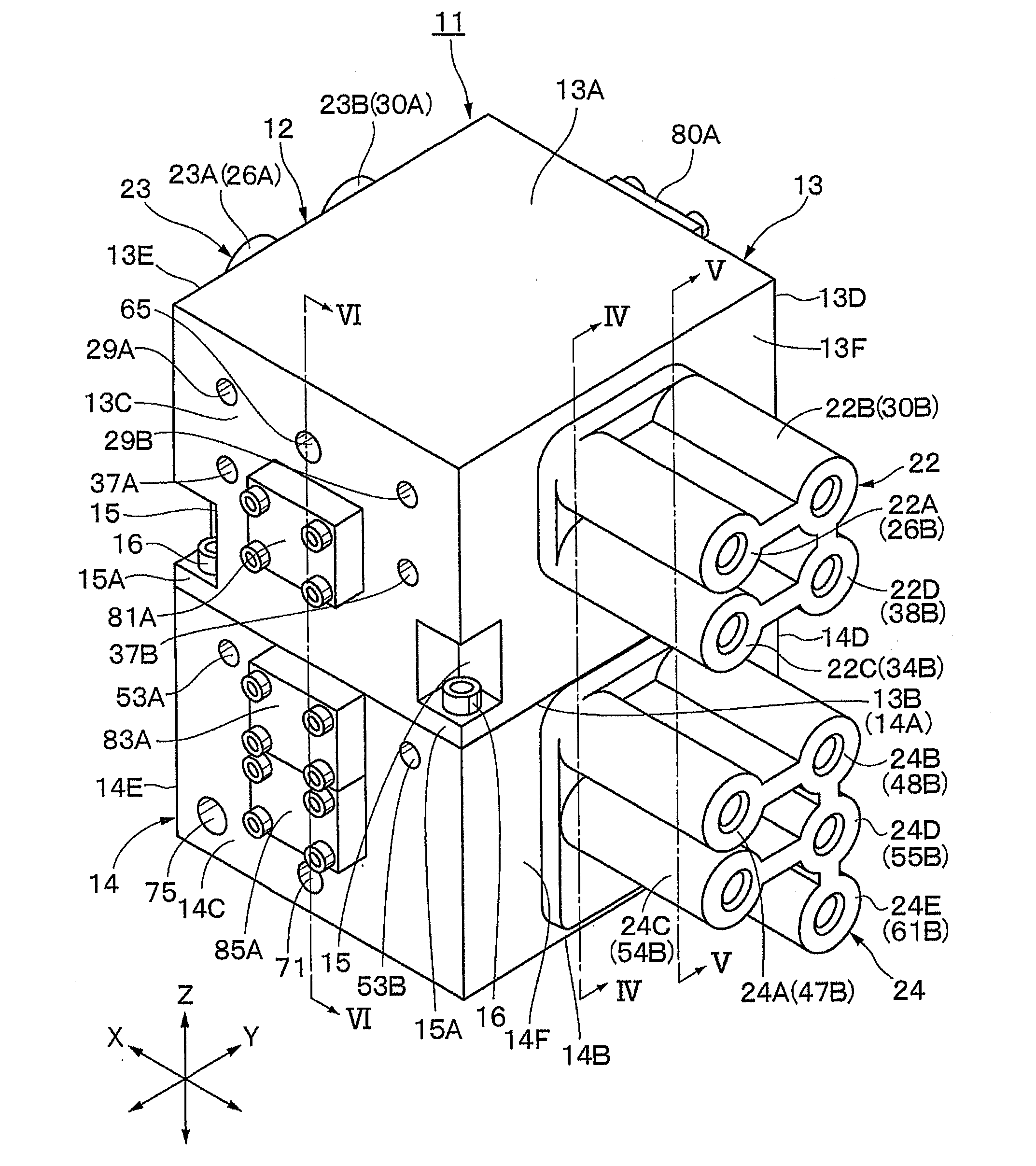
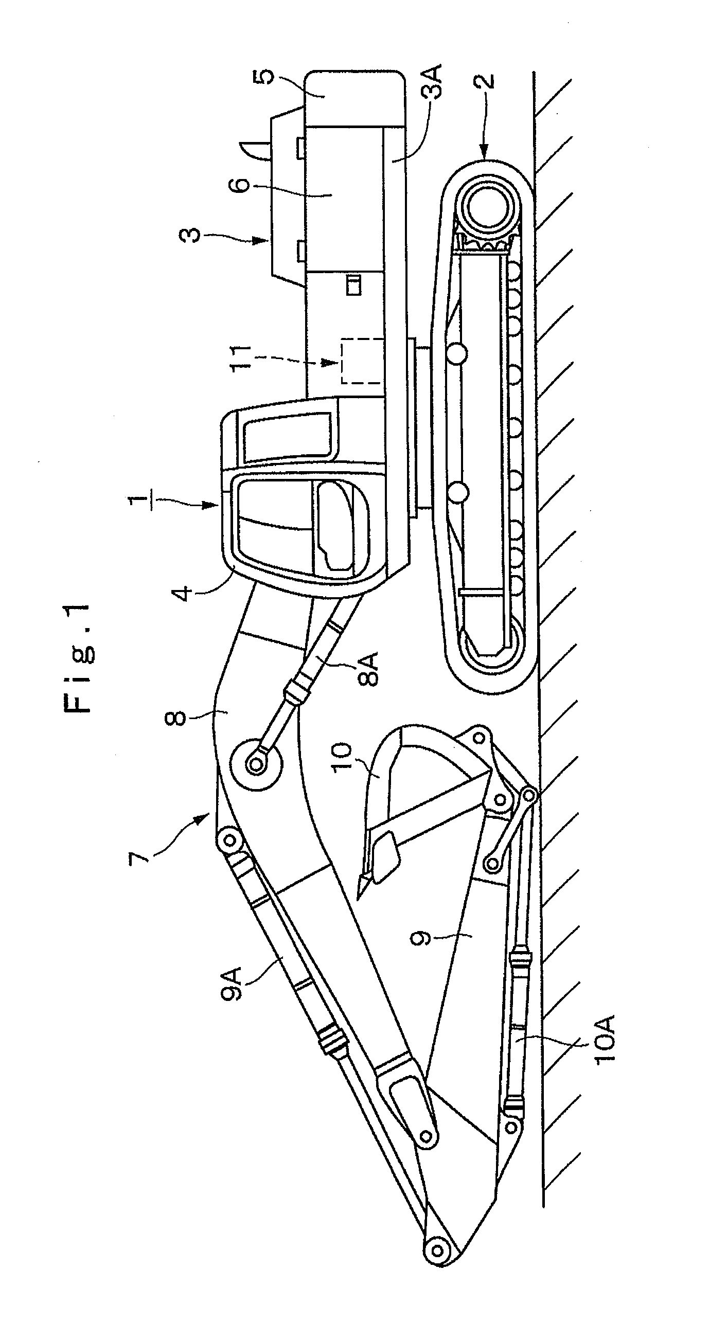
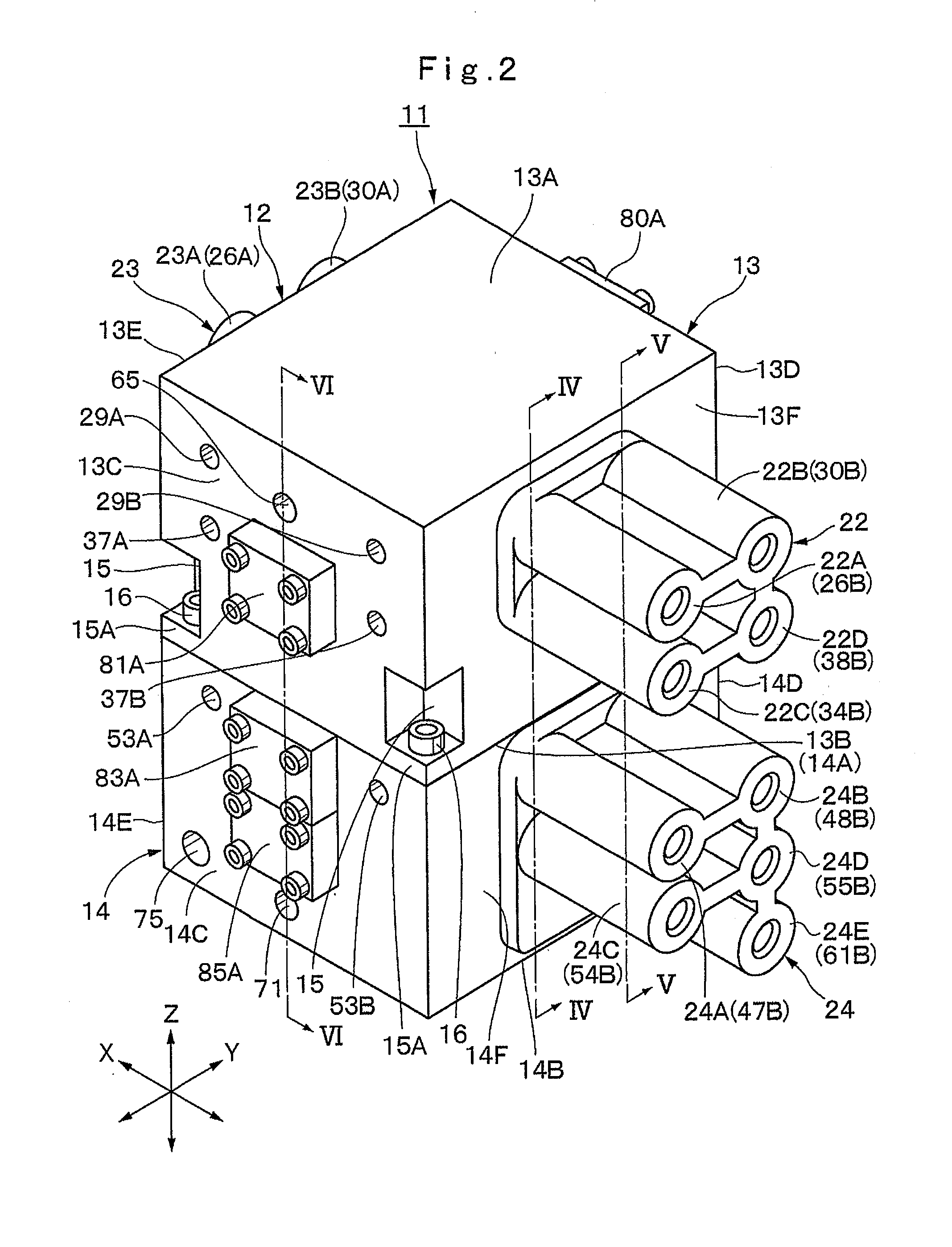
[0034]Hereinafter, an embodiment of a multiple valve device according to the present invention will be in detail explained with reference to FIGS. 1 to 14 by taking a case in which it is mounted on a hydraulic excavator as a construction machine.

[0035]In the description of the embodiment, as a representative example of the multiple valve device, an instance in which four spool sliding bores in total are provided in a first housing block and five spool sliding bores in total are provided in a second housing block are used. However, the multiple valve device according to the present invention is not limited to that, and it may be so configured that three to six spool sliding bores are provided in the first housing block and three to six spool sliding bores are provided in the second housing block in a valve housing in which six to twelve spool sliding bores are provided.

[0036]In the figure, designated at 1 is a hydraulic excavator as a construction machine, and as shown in FIG. 1, thi...


PUM


Abstract

A valve housing of a multiple valve device is formed by being split into two parts, that is, a first housing block and a second housing block abutting against and separated away from each other at positions of facing joining surfaces. Three or more spool sliding bores are provided on the first housing block forming a three-dimensional structure. The other spool sliding bores are provided on the second housing block forming a three-dimensional structure. A relief valve for suppressing maximum pressures in a plurality of oil passages to a predetermined set pressure or less is provided on one of the first and second housing blocks. This relief valve is arranged at a position closer to the joining surfaces than each of the spool sliding bores provided in the one of housing blocks.

Description

TECHNICAL FIELD[0001]The present invention relates to a multiple valve device mounted on a construction machine represented by a hydraulic excavator and suitably used for driving / control of a traveling and working hydraulic actuator.BACKGROUND ART[0002]In general, in order to supply a pressurized oil from a hydraulic source including a hydraulic pump to a hydraulic actuator (a hydraulic motor, a hydraulic cylinder, for example), a construction machine represented by a hydraulic excavator is configured to be provided with a multiple valve device composed of a plurality of spool valves (directional control valves) between the hydraulic actuator and the hydraulic source.[0003]This type of conventional-art multiple valve device includes a valve housing provided with oil passages on a hydraulic source side having a plurality of spool sliding bores and communicating with each of the spool sliding bores and an actuator side and a plurality of spools provided by being inserted in each of th...

Claims


Application Information

Patent Timeline
IPC IPC(8): F15B13/08F15B13/02
CPCF15B13/0842F15B13/024F15B13/0817E02F9/2267E02F9/2282E02F9/2285E02F9/2292F15B13/0896F16K27/003F16K27/041F15B2211/20576F15B2211/3116F15B2211/50518Y10T137/87885
Inventor KOBAYASHI, YOSHINOBUTOUGASAKI, MITSUHISAKUBOTA, SATORUMATSUZAKI, HIROSHI
Owner HITACHI CONSTR MASCH CO LTD
Why Eureka
Try Eureka