Terminal structure of extreme-low temperature equipment

a technology of terminal structure and extreme-low temperature equipment, which is applied in the direction of insulated conductors, cables, conductors, etc., can solve the problems of increasing system loss as a whole, difficulty in controlling liquid level, and difficulty in applying regenerative cooling using a closed system to the refrigerant tank, so as to prevent mechanical damage to the bushing and prevent the effect of lowering the insulation performan

Inactive Publication Date: 2005-05-03
SUMITOMO ELECTRIC IND LTD
View PDF4 Cites 17 Cited by
  • Summary
  • Abstract
  • Description
  • Claims
  • Application Information

AI Technical Summary

Benefits of technology

[0023]In addition, it is a second object of the present invention to provide a terminal structure of cryogenic equipment in which any liquefied substance is prevented from occurring in the inside of a conductor portion such as a bushing or the like, so that the lowering of insulation performance and an excessive pressure change in the inside of the conductor portion both generated with the occurrence of the liquefied substance can be suppressed.
[0050]When the air gap portion formed above the insulating oil reservoir does not communicate with the space in the conductor portion, a vacuum may be created in the space in the conductor portion or the space in the conductor portion may be filled with gas not liquefied at a very low temperature. This configuration may be attained by sealing the space in the conductor portion by welding or the like. Accordingly, any liquefied substance is prevented from occurring in the conductor portion at the very low temperature. Thus, an excessive pressure change in the bushing is suppressed so that the bushing is prevented from being mechanically damaged.

Problems solved by technology

(1) Thermal invasion from the room temperature portion 400 to the very low temperature portion 200 is large.
As a result, the energy required for the cooling becomes a loss to thereby cause increase in the system loss as a whole.
(2) Application of regenerative cooling using a closed system to the refrigerant tank is difficult.
However, when regenerative cooling is carried out with the supply pipe 22 and the discharge port 14 being closed to leave the liquid nitrogen 11 as it is, a change in pressure, a change in invading heat, and so on, make control of the liquid level be difficult.
(3) When the space inside the bushing 30 communicates with the gas reservoir 42 in the insulator 40, the insulation performance may deteriorate.
As a result, the inside of the insulator 40 becomes negative pressure, resulting in deterioration of insulation performance.
However, since a gas inlet 22 becomes a high voltage portion, shutdown of current application and attachment / detachment of pipe arrangement are required for the connection of the gas supply unit in an unrealistic sense.
However, in order to secure pressure large enough not to affect the insulation performance after cooling, the pressure before cooling should be excessive in an unrealistic sense.
Therefore, the aforementioned deterioration of the insulation performance caused by the negative pressure is insignificant.
However, it is also anticipated that the sealing of the space inside the bushing 30 is not perfect.
Thus, the very large pressure causes mechanical damage to the bushing 30.

Method used


Image

  • Terminal structure of extreme-low temperature equipment
  • Terminal structure of extreme-low temperature equipment
  • Terminal structure of extreme-low temperature equipment

Examples


first embodiment

(First Embodiment)

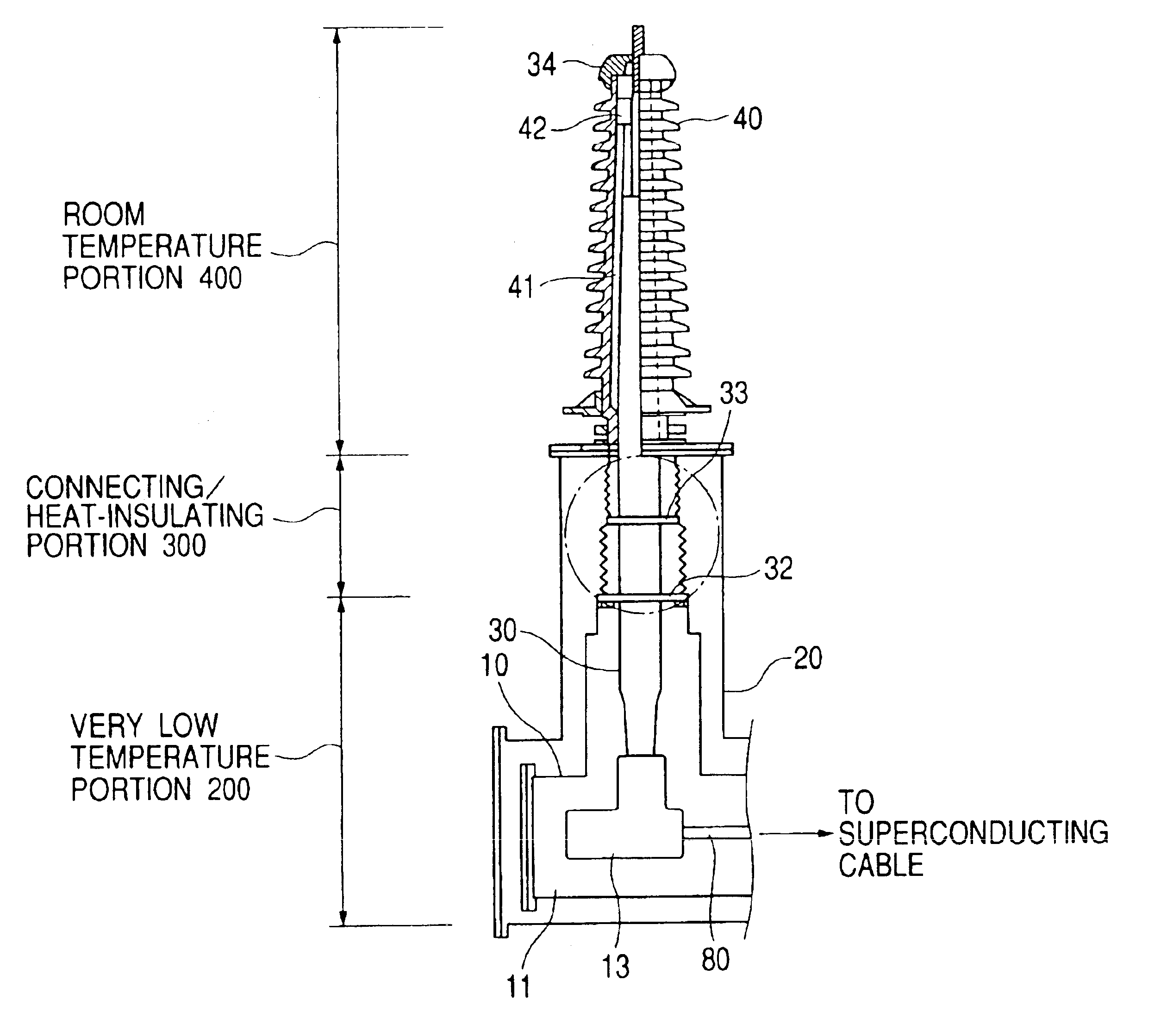
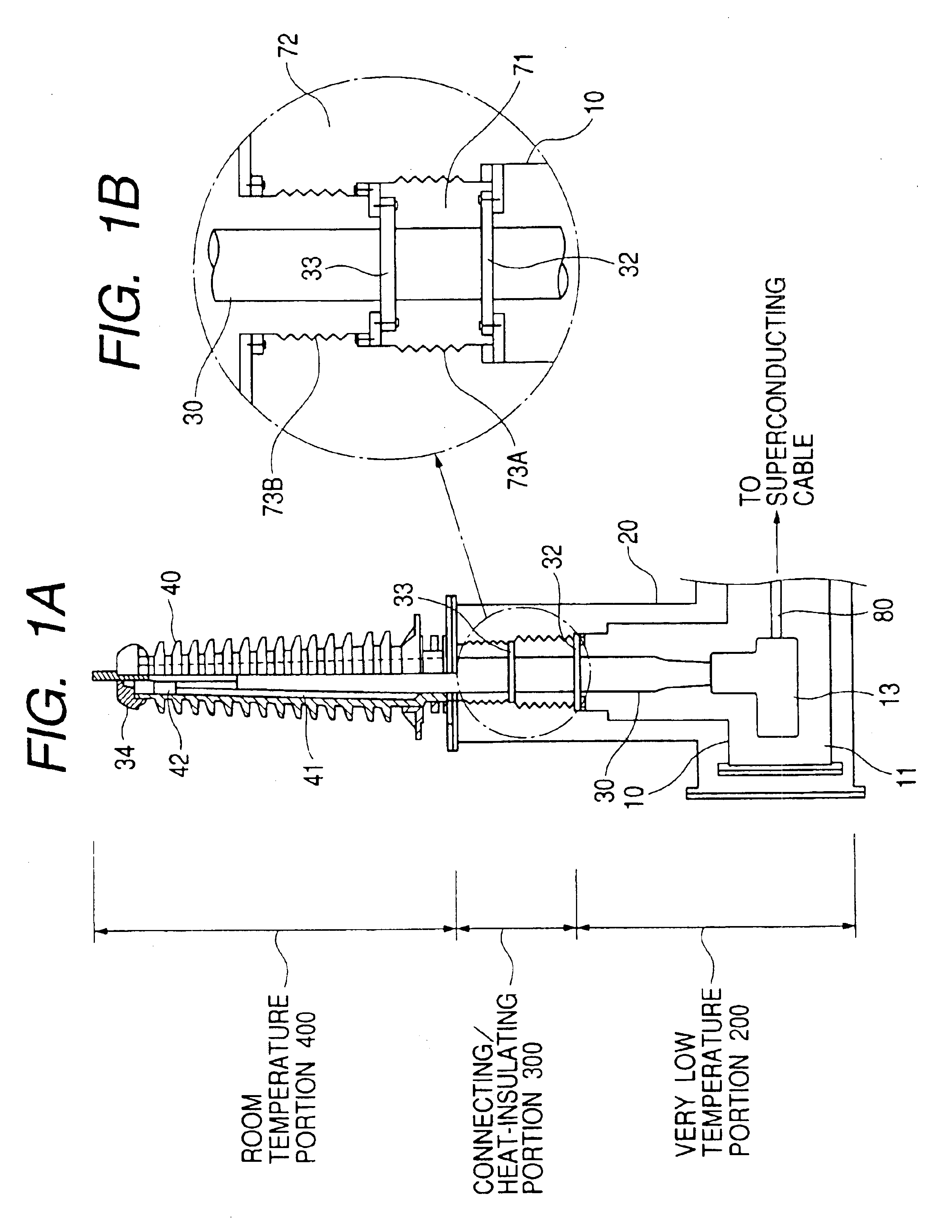
[0062]Here, a terminal structure of a superconducting cable will be described by way of example. FIG. 1A is a schematic view of a terminal structure according to the present invention, and FIG. 1B is a blow-up view of a portion of the terminal structure shown in FIG. 1A. This terminal structure has a very low temperature portion immersed in liquid nitrogen 11 in a refrigerant tank 10, a room temperature portion 400 received in an insulator 40, and a connecting / heat-insulating portion 300 formed between the very low temperature portion 200 and the room temperature portion 400.

[0063]The vacuum vessel 20 is connected to an adiabatic pipe (not shown) of a superconducting cable. A vacuum is maintained in the vacuum vessel 20, in the portion connecting with the adiabatic pipe and in the adiabatic pipe. In this embodiment, the opening diameter of the vacuum vessel 20 was set at φ600 mm.

[0064]A connecting conductor 80 connecting with the conductor of the superconducting ca...

second embodiment

(Second Embodiment)

[0080]Here, a terminal structure of a superconducting cable will described by way of example. FIG. 3 is a schematic view of a terminal structure according to the present invention. This terminal structure has a very low temperature portion 200 immersed in liquid nitrogen 111 in a refrigerant tank 110, a room temperature portion 400 received in an insulator 140, and a connecting / heat-insulating portion 300 formed between the very low temperature portion and the room temperature portion.

[0081]A connecting conductor connecting with the conductor of a not-shown superconducting cable is introduced, through a vacuum vessel 120, into the refrigerant tank 110 constituting the very low temperature portion 200. The refrigerant tank 110 is a cylindrical pipe in which the liquid nitrogen 111 is enclosed hermetically. The aforementioned connecting conductor is connected to a bushing 130 (conductor portion) in the refrigerant tank.

[0082]The refrigerant tank 100 configured thus ...

third embodiment

(Third Embodiment)

[0092]Next, FIG. 4 shows an embodiment having a different configuration in its room temperature portion. The third embodiment has the same configuration as that of the first embodiment, except that the configuration of an end portion of the room temperature portion is different. Therefore, description will be made chiefly on the different point.

[0093]This room temperature portion has a configuration in which a bushing 130 is received in an insulator, but a space 134 formed inside the bushing 130 does not communicate with an air gap portion 142 formed above an insulating oil reservoir. In this case, a vacuum is created in the space inside the bushing or the space inside the bushing is filled with helium gas not liquefied at the very low temperature. The space inside the bushing is sealed by welding the end portions of a stainless steel pipe 131, or the like. With such a configuration, any liquefied substance is restrained from occurring inside the bushing so as to s...


PUM

PropertyMeasurementUnit
boiling pointaaaaaaaaaa
temperatureaaaaaaaaaa
structureaaaaaaaaaa

Abstract

A terminal structure of cryogenic equipment for leading a terminal of cryogenic equipment 100 from a very low temperature portion to a room temperature portion through a bushing, having a feature in that a connecting / heat-insulating portion 300 adiabatically connected with the aforementioned very low temperature portion 200 and the aforementioned room temperature portion 400 is provided along the outer circumference of the aforementioned bushing 30 between the aforementioned very low temperature portion 200 and the aforementioned room temperature portion 400.

Description

TECHNICAL FIELD[0001]The present invention relates to a terminal structure for leading a conductor of cryogenic equipment from very low temperature to room temperature. Particularly it relates to a terminal structure superior in adiathermancy or insulation performance.BACKGROUND ART[0002]FIG. 7 is a schematic view showing a conventional terminal structure for cryogenic equipment.[0003]This terminal structure has a terminal of cryogenic equipment 100 (not shown), a refrigerant tank 10 for receiving the terminal, a bushing 30 for securing electric conduction from a conductor of the vacuum vessel 20 to a room temperature portion, a vacuum vessel 20 covering the outside of the refrigerant tank 10, and an insulator 40 connected to an upper portion of the vacuum vessel 20 so as to protrude therefrom.[0004]The bushing 30 is connected, substantially at right angles, to a superconductor led in from the cryogenic equipment 100. The bushing 30 has a conductor in its core, and is circumferentia...

Claims


Application Information

Patent Timeline
Patent Type & Authority Patents(United States)
IPC IPC(8): H02G15/00H02G15/22H02G15/34
CPCH02G15/34H01B17/36
Inventor ASHIBE, YUUICHIHIROSE, MASAYUKIFURUKAWA, KOUHEITAKAHASHI, YOSHIHISAMATSUO, KIMIYOSHIHONJO, SHOICHIMIMURA, TOMOOAIBA, TERUMITSU
Owner SUMITOMO ELECTRIC IND LTD
Why Eureka
Try Eureka