Control device

a control device and input shaft technology, applied in mechanical equipment, propulsion parts, transportation and packaging, etc., can solve the problems of affecting the speed change time, and the rotational speed of the input shaft may be unlikely to vary to prolong the speed change time uselessly, so as to achieve the effect of suppressing the occurrence of speed change shocks, suppressing the occurrence of sudden changes in the rotational speed of the input shaft, and maintaining high energy efficiency

Active Publication Date: 2011-10-06
AISIN AW CO LTD
View PDF4 Cites 16 Cited by
  • Summary
  • Abstract
  • Description
  • Claims
  • Application Information

AI Technical Summary

Benefits of technology

[0032]According to the tenth aspect, the special speed change control is executed during the off-upshift regeneration. As a result, it is possible to maintain a state in which a part of the rotational drive force from the output member is transferred to the input member via the disengagement element over the entire speed change process. Therefore, even in the case where the rotary electric machine is outputting relatively high negative torque during the off-upshift regeneration, abrupt variations in rotational speed of the input shaft can be suppressed because of the rotational drive force transferred from the output member, compared to a case where a normal engagement / disengagement shift is performed so that the disengagement element is completely disengaged relatively quickly in the initial stage of the speed change process, for example. Hence, occurrence of a speed change shock can be suppressed compared to such a case. In this event, the off-upshift regeneration can be performed with no particular restriction on the magnitude of the regenerative torque produced by the rotary electric machine. Hence, the energy efficiency can be maintained high without causing an inconvenience such as a reduction in energy to be regenerated. That is, it is possible to both suppress occurrence of a speed change shock and improve the energy efficiency.
[0033]According to the characteristic configuration of the present invention, as has been described so far, in the case where slipping of the disengagement element is not detected within a predetermined time after the disengagement hydraulic pressure is lowered, the pressure increase correction is performed to raise the engagement hydraulic pressure in order to start the speed change process early. Hence, the energy efficiency can be improved early while suppressing occurrence of a speed change shock. Thus, the control device according to the present invention executes the special speed change control particularly suitably in a situation where the transmission device including, as a drive force source, the rotary electric machine capable of producing regenerative torque on the basis of a request to decelerate the vehicle performs the off-upshift regeneration.

Problems solved by technology

Therefore, the rotational speed of the input member may be unlikely to vary to extend the speed change time uselessly.
When the speed change time is extended to be long, shift feeling may be deteriorated.
Such a problem tends to occur especially in the case where the hydraulic pressure of hydraulic oil for an engagement element, which is a friction engagement element to be engaged, is low because of variations in individual quality, for example, because the rotational speed of the input member cannot be sufficiently increased or reduced via the engagement element.

Method used


Image

  • Control device
  • Control device
  • Control device

Examples


Embodiment Construction

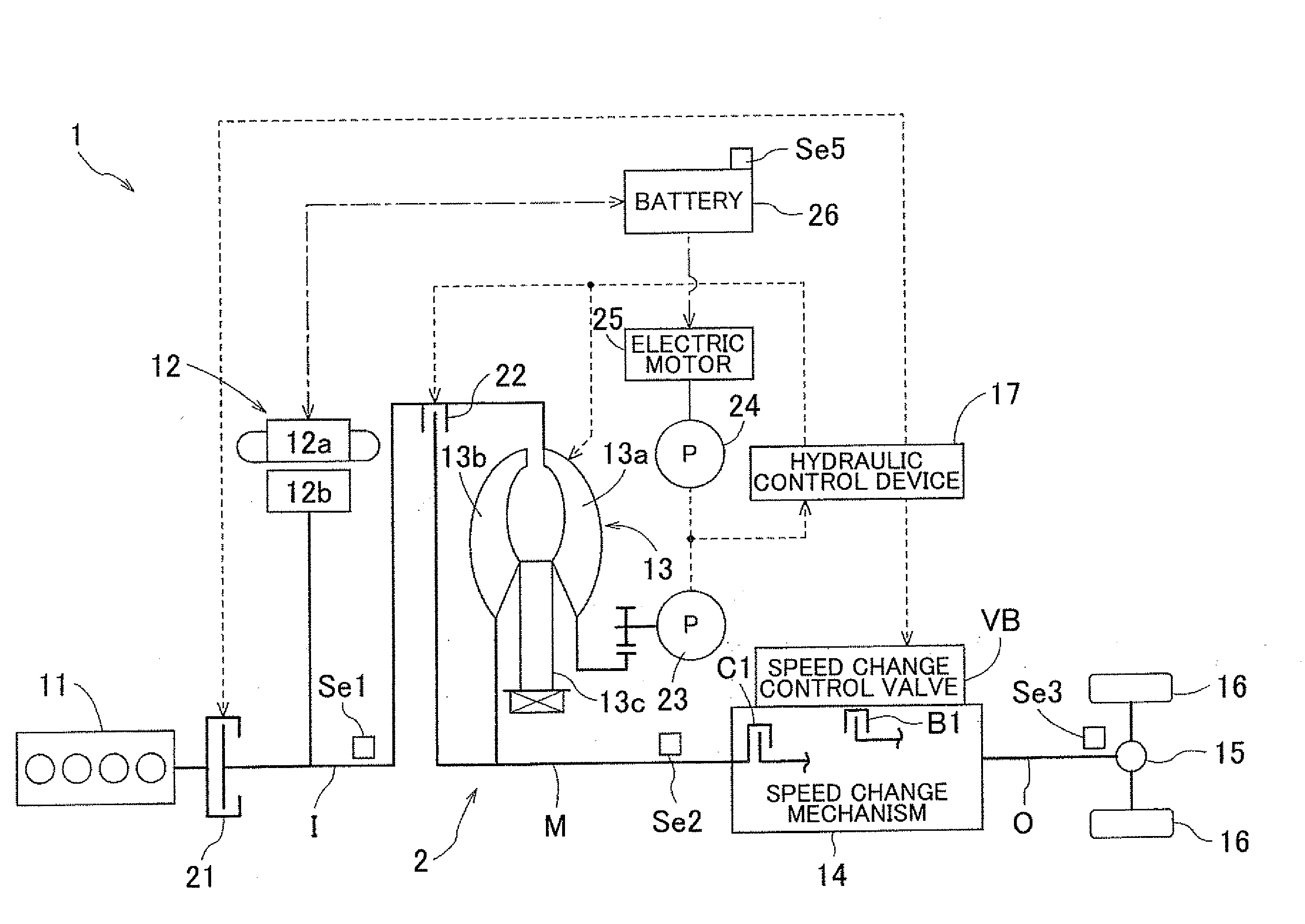
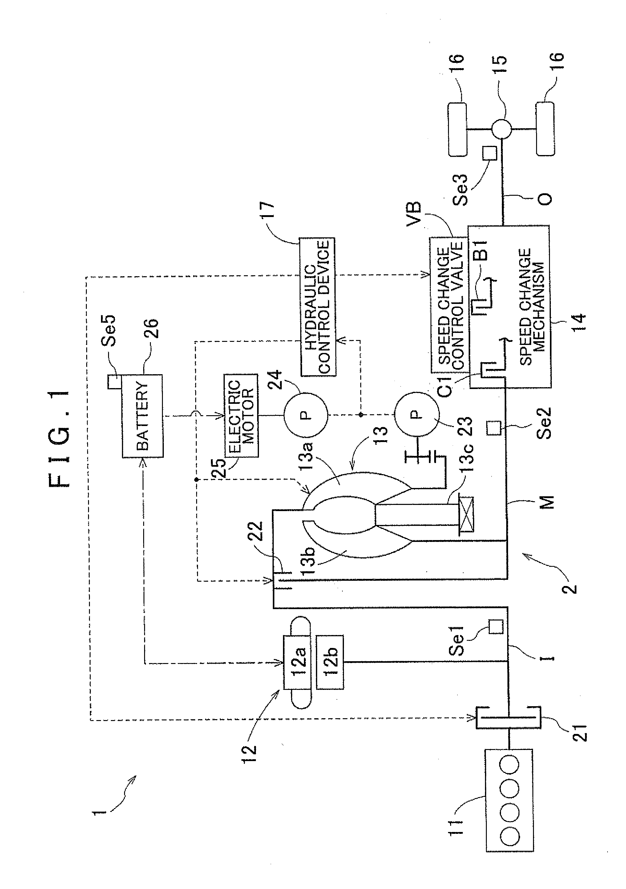
[0054]An embodiment of the present invention will be described with reference to the drawings. In the embodiment, a control device according to the present invention is applied to a transmission device 2 forming a part of a vehicle drive device 1 for a hybrid vehicle. FIG. 1 is a schematic diagram showing the configuration of a drive transfer system and a hydraulic control system of the vehicle drive device 1 including the transmission device 2 according to the embodiment. In the drawing, the solid lines each indicate a drive force transfer path, the broken lines each indicate a hydraulic oil supply path, and the dash-dotted line indicates an electric power supply path. As shown in the drawing, the vehicle drive device 1 according to the embodiment generally includes an engine 11 and a rotary electric machine 12 each serving as a drive force source. Drive forces of the drive force sources are transferred to wheels 16 via a torque converter 13 and a speed change mechanism 14. The veh...


PUM


Abstract

A control device for controlling a transmission device configured such that when the speed change mechanism performs switching to a shift speed with a different speed ratio, special speed change control is executed in which a disengagement hydraulic pressure, is lowered to cause a disengagement element to slip, and in which the disengagement element is maintained in a slipping state over an entire speed change process. In the case where slipping of the disengagement element is not detected within a predetermined time after the disengagement hydraulic pressure is lowered at start of the special speed change control, pressure increase correction is performed in which an engagement hydraulic pressure, which is a hydraulic pressure of hydraulic oil for an engagement element that is a friction engagement element to be engaged, is raised until slipping of the disengagement element is detected.

Description

INCORPORATION BY REFERENCE[0001]The disclosure of Japanese Patent Application No. 2010-086554 filed on Apr. 2, 2010 including the specification, drawings and abstract is incorporated herein by reference in its entirety.BACKGROUND OF THE INVENTION[0002]The present invention relates to a control device for controlling a transmission device including an input member drivably coupled to a drive force source, an output member drivably coupled to wheels, and a speed change mechanism that has a plurality of friction engagement elements that are controllably engaged and disengaged to switch between a plurality of shift speeds, and that outputs rotation of the input member to the output member while changing the rotational speed with a speed ratio of each shift speed.DESCRIPTION OF THE RELATED ART[0003]A vehicle drive device including a transmission device having an input member drivably coupled to an engine serving as a drive force source, an output member drivably coupled to wheels, and a ...

Claims


Application Information

Patent Timeline
Patent Type & Authority Applications(United States)
IPC IPC(8): F16H59/00B60K6/48B60K6/54B60W10/10B60W20/00F16H61/06F16H63/50
CPCF16H61/061B60L2240/486B60K6/48B60W2510/102B60L2240/423Y02T10/642F16H2059/465B60W20/00F16H2059/425Y10T74/20024B60W2710/083Y02T10/6221B60W30/19Y10T477/688B60W10/08Y02T10/62Y02T10/64B60W20/30
Inventor HASE, SHIGEKAZUUENO, HIROYAINAGAKI, NOBUAKIIWAI, NOBUHIROTSUTSUI, HIROSHI
Owner AISIN AW CO LTD
Why Eureka
Try Eureka