Fluid Machinery

a technology of fluid machinery and piston pumps, which is applied in the direction of positive displacement liquid engines, piston pumps, liquid fuel engines, etc., can solve the problems of reducing the lubrication state of each sliding section in the crank chamber, and achieves the effect of reducing the risk of a decrease in the volumetric efficiency of the piston pump, reducing the risk of a decrease in lubrication performance, and gasifying easily

Inactive Publication Date: 2015-04-09
SANDEN CORP
View PDF15 Cites 3 Cited by
  • Summary
  • Abstract
  • Description
  • Claims
  • Application Information

AI Technical Summary

Benefits of technology

[0009]According to the fluid machinery, since the interior of the crank chamber is set to a state in which the liquid-phase refrigerant is easily gasified, by allowing the refrigerant outlet section, through which the refrigerant after expansion is discharged from the expander, to communicate with the crank chamber of the piston pump, it is possible to reduce an amount of liquid-phase refrigerant that flows into the crank chamber and / or is stored in the crank chamber. Furthermore, there is little fear of gasification of the drawn refrigerant of the pump as in the above-described related arts. This can reduce the risk of a decrease in volumetric efficiency of the piston pump, while reducing a decrease in lubrication performance of the mechanical sliding section of the piston pump.

Problems solved by technology

In this case, a liquid-phase refrigerant drawn into the piston pump might flow into a crank chamber, and thus, there may be a concern over degradation of a lubrication state of each sliding section in the crank chamber.

Method used


Image

  • Fluid Machinery
  • Fluid Machinery
  • Fluid Machinery

Examples


Embodiment Construction

[0018]Hereinafter, embodiments of the present invention will be described with reference to the accompanying drawings.

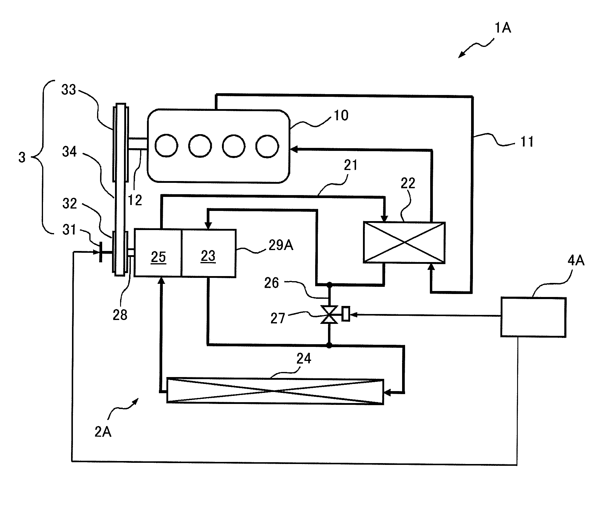
[0019]FIG. 1 illustrates a schematic configuration of an exhaust heat recovery apparatus 1A to which a fluid machinery according to the present invention is applied in a first embodiment. The exhaust heat recovery apparatus 1A is mounted on a vehicle and recovers and uses exhaust heat of an engine 10 of the vehicle.

[0020]The exhaust heat recovery apparatus 1A has a Rankine cycle 2A that recovers the exhaust heat of the engine 10 and converts it into power, a transmission mechanism 3 that performs the transmission of power between the Rankine cycle 2A and the engine 10, and a control unit 4A that controls the overall operation of the exhaust heat recovery apparatus 1.

[0021]The engine 10 is a water-cooled internal combustion engine and is cooled by an engine cooling water that circulates in a cooling water flow passage 11. A heater 22 of the Rankine cycle 2A to be desc...


PUM


Abstract

A fluid machinery including: an expander that generates power by expansion of refrigerant; and a piston pump that pumps the refrigerant, and capable of reducing a decrease in lubrication performance of a mechanical sliding section in a crank chamber of the piston pump. A fluid machinery 29A includes an expander unit (scroll expander) 60A that generates power by expansion of refrigerant, and a pump unit (piston pump) 50A that pumps the refrigerant. A rotating shaft 28 of the fluid machinery 29A functions as an output shaft of the expander unit 60A and a drive shaft of the pump unit 50A. The rotating shaft 28 has a crank section 28a housed in the crank chamber 72A. A refrigerant outlet chamber 78A, through which the expanded refrigerant is discharged from the expander unit 60A, communicates with the crank chamber 72A via a bearing 71b, a housing space of a driven crank mechanism 80, and an anti-rotation member 77.

Description

TECHNICAL FIELD[0001]The present invention relates to a fluid machinery used by being incorporated into a Rankine cycle or the like, in particular, relates to a fluid machinery that is provided with an expander that generates power by expansion of a refrigerant, and a piston pump that pumps the refrigerant.BACKGROUND ART[0002]As a fluid machinery incorporated into a Rankine cycle, a pump-integrated expander in which an expander that generates power by expansion of a refrigerant is integrally connected to a pump that pumps the refrigerant has been known (for example, see Patent Document 1). Inventors have considered adopting a piston pump, with high volumetric efficiency from a low rotational speed area to a high rotational speed area, as a pump of the fluid machinery of this type. In this case, a liquid-phase refrigerant drawn into the piston pump might flow into a crank chamber, and thus, there may be a concern over degradation of a lubrication state of each sliding section in the ...

Claims


Application Information

Patent Timeline
Patent Type & Authority Applications(United States)
IPC IPC(8): F04B53/18
CPCF04B53/18F01C1/0215F01C11/008F01C13/04F01C21/18F04B9/12F04B23/103F04B23/12F04B53/08
Inventor NAKAMURA, SHINJI
Owner SANDEN CORP
Why Eureka
Try Eureka