
Rotary positive displacement hydraulic machines

a hydraulic machine and positive displacement technology, applied in the direction of rotary piston engines, rotary or oscillating piston engines, intermeshing engagement engines, etc., can solve the problems of increasing the radial clearance loss, reducing the volumetric efficiency of the machine, and allowing one or both bearing supports to move relativ

Inactive Publication Date: 2007-09-04
LIPSCOMBE BRIAN ROBERT
View PDF8 Cites 0 Cited by
  • Summary
  • Abstract
  • Description
  • Claims
  • Application Information

AI Technical Summary

Benefits of technology

[0005]In order to ensure good volumetric efficiency, it is important that liquid clearance losses between the low and high pressure sides of the pump are kept to a minimum. It is also important to maintain proper alignment of the bearings as otherwise the performance and durability of the bearings will decrease. The high pressure on the outlet or delivery side of the pump causes the housing to deflect and can also cause one or both bearing supports to move relative to the housing. This increases the radial clearance losses thus reducing the volumetric efficiency of the machine. It can also cause the bearings to move out of alignment, particularly in “pot-bodied” machines where the deflection occurs at one end only.

Problems solved by technology

The high pressure on the outlet or delivery side of the pump causes the housing to deflect and can also cause one or both bearing supports to move relative to the housing.
This increases the radial clearance losses thus reducing the volumetric efficiency of the machine.
It can also cause the bearings to move out of alignment, particularly in “pot-bodied” machines where the deflection occurs at one end only.
The non-circular inner rim and matching non-circular recess are difficult to machine accurately and require complex CNC programming.
The end cover is secured to the housing by bolts and this axial clearance results in a bolt load overhang which imposes a considerable bending load on the flange profile.

Method used


Image

  • Rotary positive displacement hydraulic machines
  • Rotary positive displacement hydraulic machines
  • Rotary positive displacement hydraulic machines

Examples


Embodiment Construction

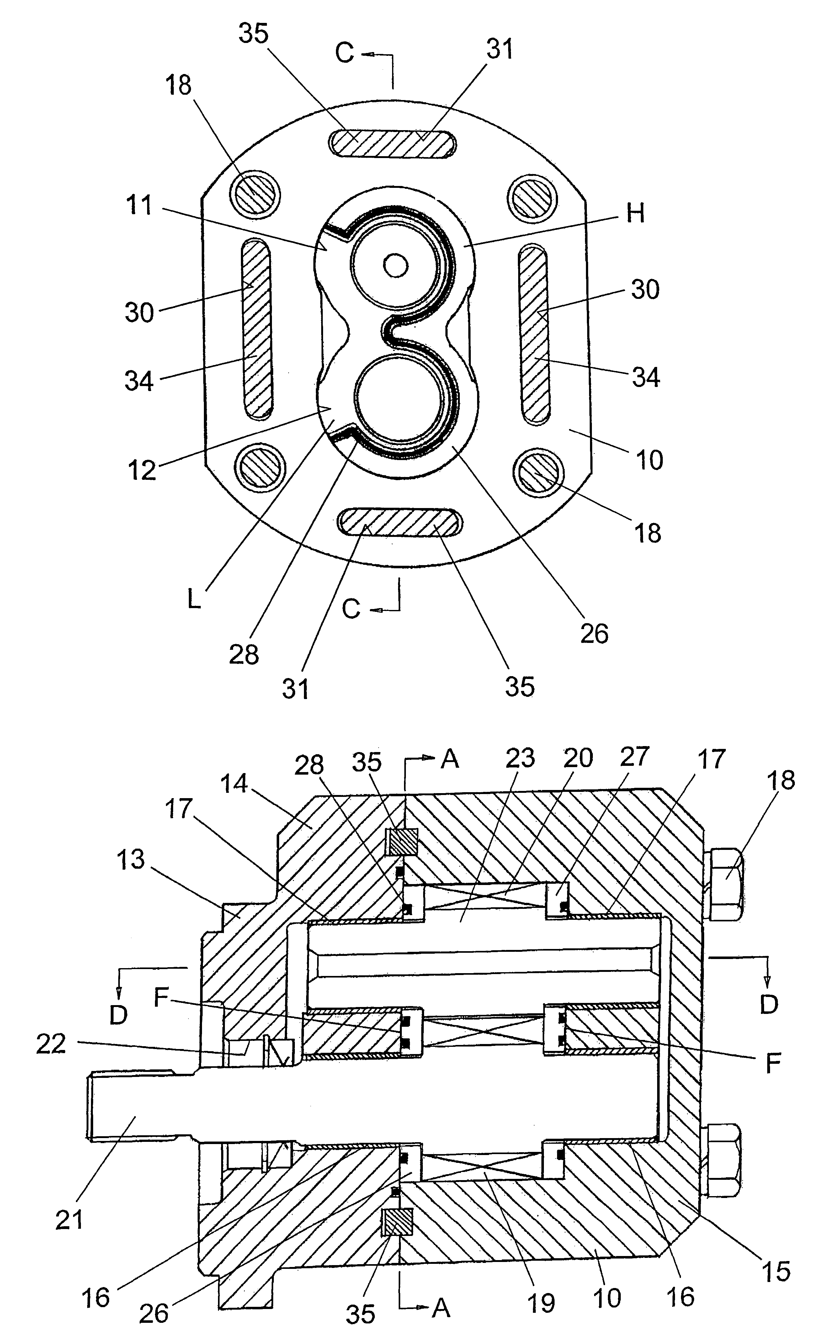
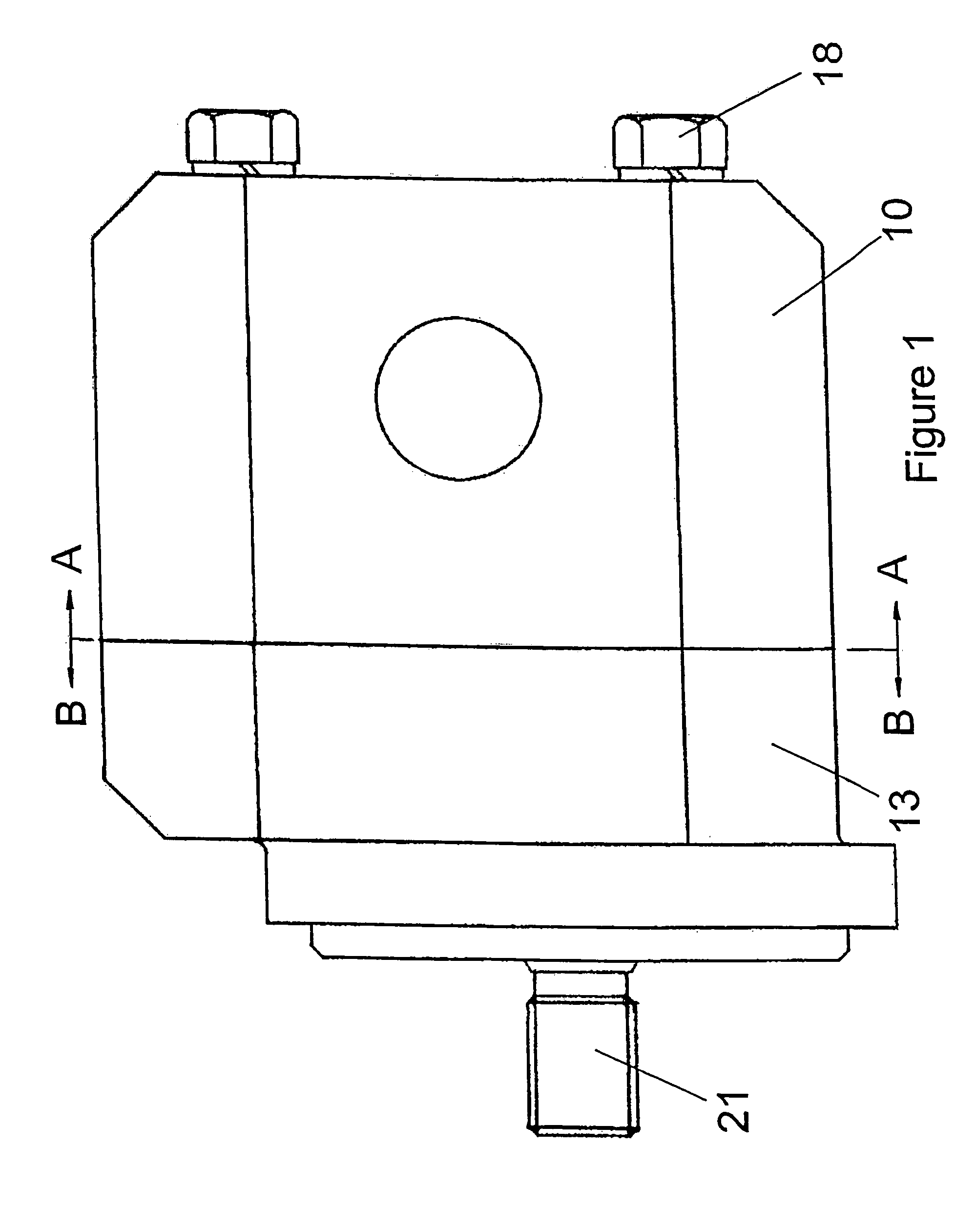
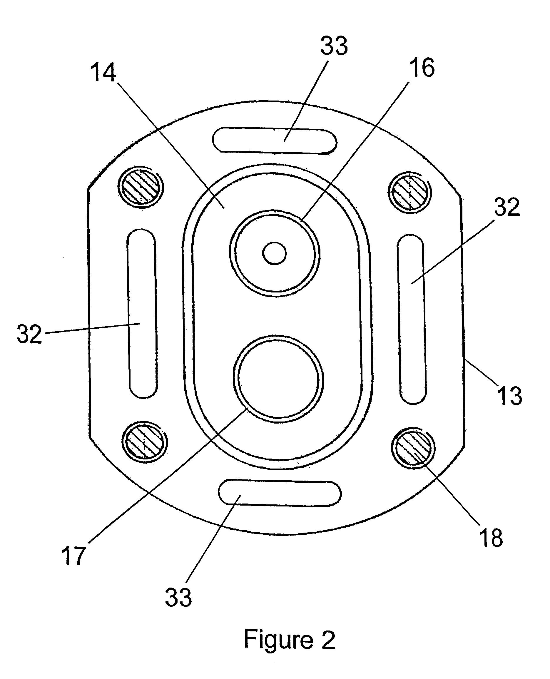
[0018]Referring firstly to FIGS. 1 to 6 of the drawings, the positive displacement hydraulic machine shown therein is in the form of a gear pump, although it could be in the form of a motor. The pump has a pump body comprising a housing 10 which defines two mutually intersecting parallel working chambers 11 and 12. The housing is “pot-bodied” and closed at one end. The other open end of the housing 10 is closed by an end cover 13.

[0019]The closed end of the housing 10 and the end cover 13 have integral one piece bearing supports 14 and 15, respectively, each of which supports two sleeve bearings 16 and 17. The end cover 13 is clamped to the housing 10 by bolts 18.

[0020]Two meshing pump rotors in the form of gears 19 and 20 are mounted for rotation in the chambers 11 and 12, respectively. The gear 19 is integral with a drive shaft 21 which is supported in the sleeve bearings 16 in the two bearing supports 14 and 15 and which passes through an aperture 22 in the end cover 13 so that i...


PUM


Abstract

A rotary positive displacement hydraulic machine includes a housing defining two mutually intersecting parallel working chambers having a low pressure inlet side and a high pressure outlet side. Two meshing rotors are mounted for rotation in the two chambers, respectively. Bearing supports at opposite ends of the chambers, support bearings in which the rotors are journalled for rotation. At least one end of the housing is closed by an end cover. The end cover and adjacent housing end have at least one elongate recess on each side of the working chambers. The end cover recesses are alignable with the housing recesses. There is at least one keying element in each pair of aligned recesses so that the open end of the housing is supported against relative movement by differential fluid pressure in the chambers in a direction transverse to a plane containing the axes of rotation of the meshing rotors.

Description

INTRODUCTION[0001]This invention relates to rotary positive displacement hydraulic machines in the form of gear pumps and motors.[0002]Rotary positive displacement machines, in the form of gear pumps and motors, generally comprise a housing having two mutually intersecting parallel working chambers, two meshing rotors mounted for rotation in the two chambers, respectively, and two bearing supports at opposite ends of the chambers and each supporting bearings in which the two rotors are journalled for rotation.[0003]A common design is for the housing to have only one open end which is closed by a separate end cover having an integral bearing support. These are known as “pot-bodied” machines. It is, however, also known to provide the housing with two open ends each of which is closed by a separate end cover. Some such designs have the bearing supports integral with the end covers. Others have the bearing supports in the open ended housing. The end covers which are not integral with th...

Claims


Application Information

Patent Timeline
Patent Type & Authority Patents(United States)
IPC IPC(8): F01C19/08F03C2/00F04C2/00F04C2/08F04C2/18
CPCF04C2/086F04C2/18F04C2230/603F04C13/00
Inventor LIPSCOMBE, BRIAN ROBERT
Owner LIPSCOMBE BRIAN ROBERT
Learn More