Filter capsule

Active Publication Date: 2010-11-11
SARTORIUS STEDIM BIOTECH GMBH
View PDF7 Cites 14 Cited by
  • Summary
  • Abstract
  • Description
  • Claims
  • Application Information

AI Technical Summary

Benefits of technology

[0016]The arrangement of the air release valve in the recess of the end cap has the advantage that the air release valve is protected practically on all sides. The side surfaces and the base surfaces of the recess are substantially perpendicular to the protective wall or to the bottom of the recess. The mutually opposite side surfaces of the recess can also be oblique in relation to the bottom, i.e. have a greater spacing toward the end face of the end cap. The end face of the end cap at the same time forms a kind of second protective wall, so that the air release valve is embedded between two protective walls. Here too, it is important that the side walls are at such a distance from the air release valve that the air release valve is easy to operate manually.
[0017]According to another preferred embodiment of the invention, a housing inlet and a housing outlet are arranged transverse to the longitudinal axis of the filter housing on a first end cap. The housing inlet is connected to a non-filtrate chamber arranged upstream of a filter in the filter housing. The housing outlet is connected to a f

Problems solved by technology

Air release valves that are at the highest point disadvantageously protrude beyond the wall of the filter capsule or end cap in the direction of the longitudinal axis or occasionally transverse to the longitudinal axis.
These air release valves, particularly those of plastic filter capsules, are susceptible to breaking off if used improperly.
However, the packaging film may be damaged by the air release valve an

Method used


Image

  • Filter capsule
  • Filter capsule
  • Filter capsule

Examples


Example

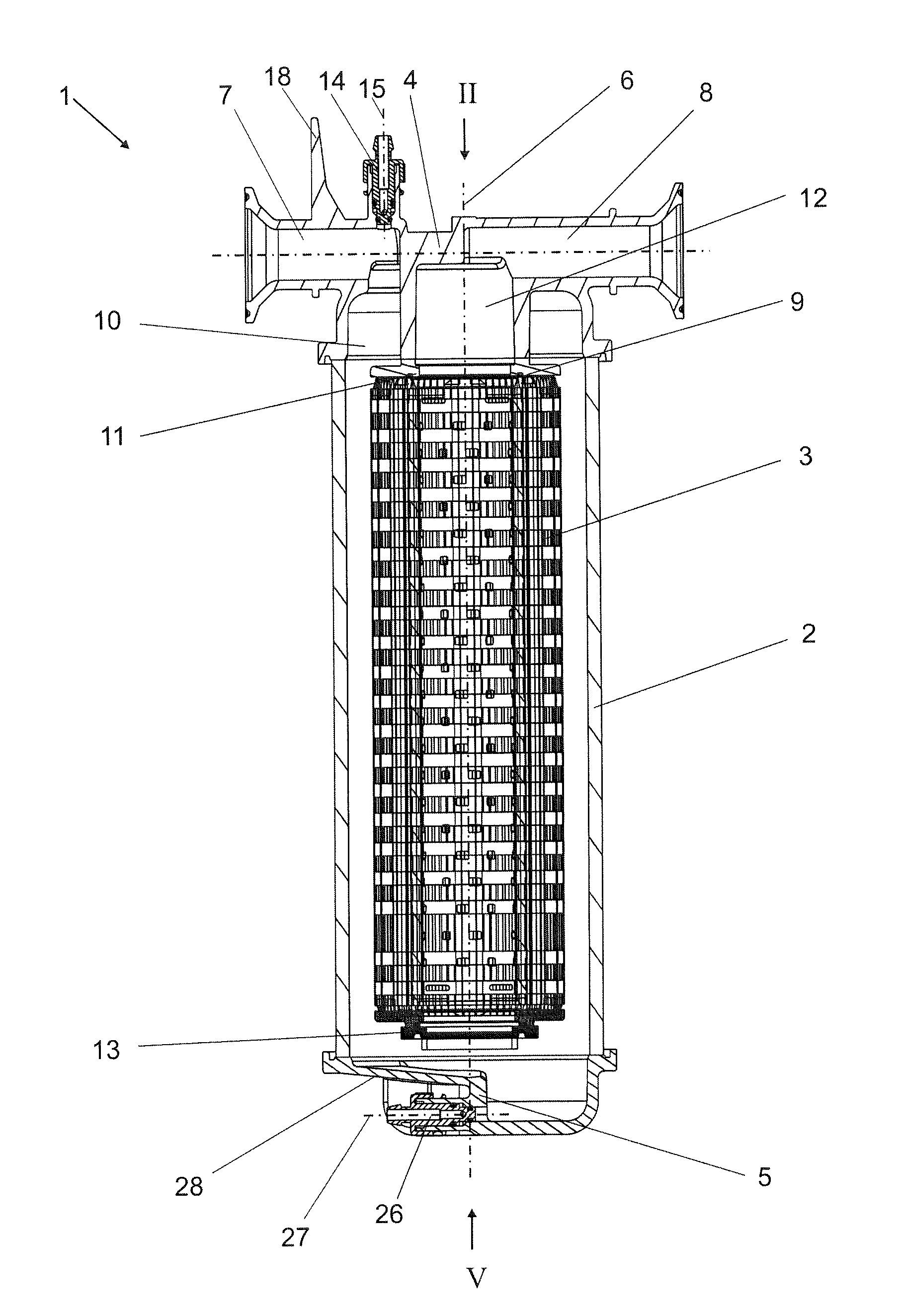
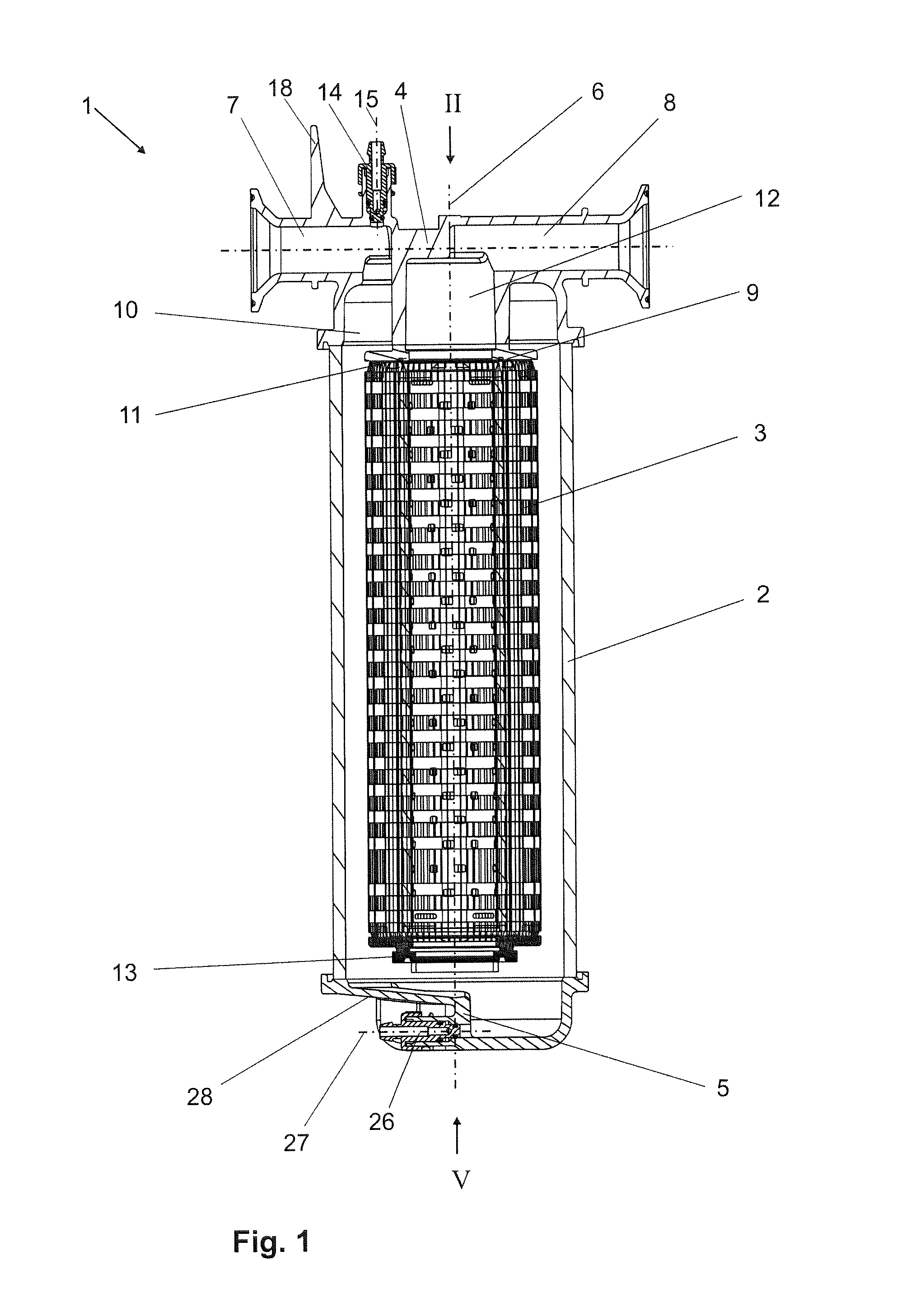
[0027]A filter capsule for filtering liquid media is identified generally by the numeral 1 in FIG. 1. The filter capsule 1 is composed principally of a filter housing 2 with a filter 3, a first end cap 4 and a second end cap 5.

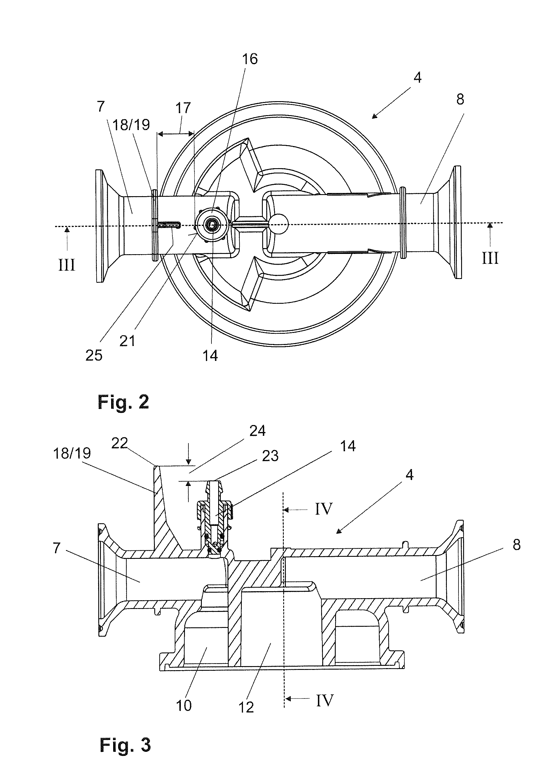
[0028]The first end cap 4 has a housing inlet 7 and a housing outlet 8 transverse to the longitudinal axis 6 of the filter housing 2.

[0029]The filter 3 is secured with its first end 9 on the first end cap 4, in this example by welding. A non-filtrate chamber 10 is arranged between the filter 3 and the filter housing 2 and is connected to the housing inlet 7. The filter 3 has an inner tube 11 with an interior that forms a filtrate chamber 12, which is connected to the housing outlet 8. The filter housing 2 has a second end directed away from the first end cap 4 and the second end cap 5 is at the second end of the filter housing 2. The filter 3 has a closed, free end 13 arranged at a distance from the second end cap 5.

[0030]The first end cap 4 has an air release...


PUM

PropertyMeasurementUnit
Widthaaaaaaaaaa
Circumferenceaaaaaaaaaa

Abstract

A filter capsule has a filter housing which, on at least one end face, has an end cap with an air release valve. A protective wall is formed on the end cap at a distance from the air release valve and protrudes beyond the air release valve.

Description

BACKGROUND OF THE INVENTION[0001]1. Field of the invention.[0002]The invention relates to a filter capsule with a filter housing which, on at least one end face, has an end cap with an air release valve.[0003]2. Description of the Related Art.[0004]Plastic filter capsules suitable for disposal after one use are employed increasingly in biotechnology. More particularly, increasing use is being made of filter capsules with the inflow and outflow configured in a T-style design. Thus, the housing inlet and outlet are arranged on one end, or on one end cap, of the filter capsule. The housing inlet and the housing outlet, in this case, are designed in a T-shape so that they each are arranged transverse to the longitudinal axis of the filter housing and are connected at an angle to the non-filtrate chamber and filtrate chamber, respectively.[0005]An air release valve is required to avoid a gas volume developing at the upper end of the non-filtrate chamber if the two connection pieces are a...

Claims


Application Information

Patent Timeline
IPC IPC(8): B01D35/01
CPCB01D36/001B01D27/08
Inventor PRADEL, GUENTERROEHL, MAIK
Owner SARTORIUS STEDIM BIOTECH GMBH
Why Eureka
Try Eureka