

Apparatus and methods for repairing the function of a diseased valve and method for making same
a diseased valve and apparatus technology, applied in the field of apparatus and methods for repairing the function of a diseased valve, can solve the problems of chronic venous insufficiency, incompetent venous valve, and so severe congenital valve abnormalities
- Summary
- Abstract
- Description
- Claims
- Application Information
AI Technical Summary
Benefits of technology
Problems solved by technology
Method used
Image

Examples
first embodiment
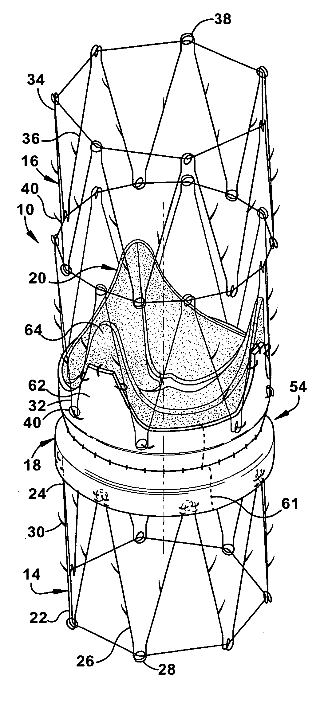
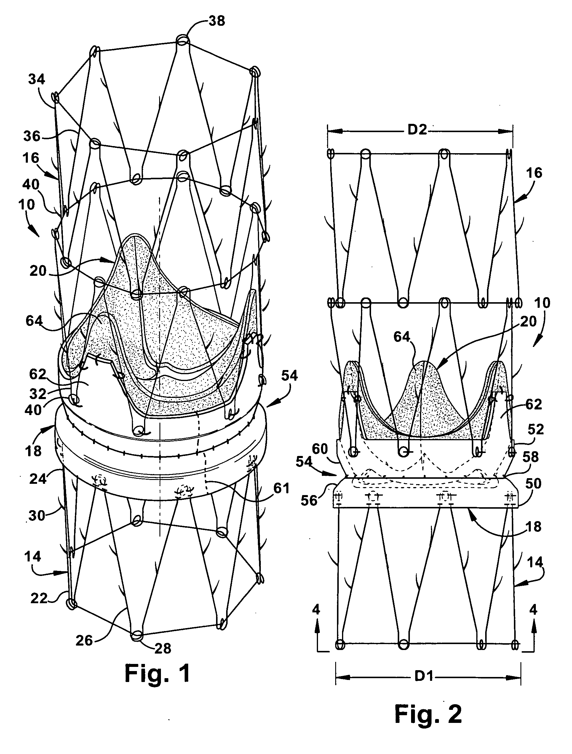
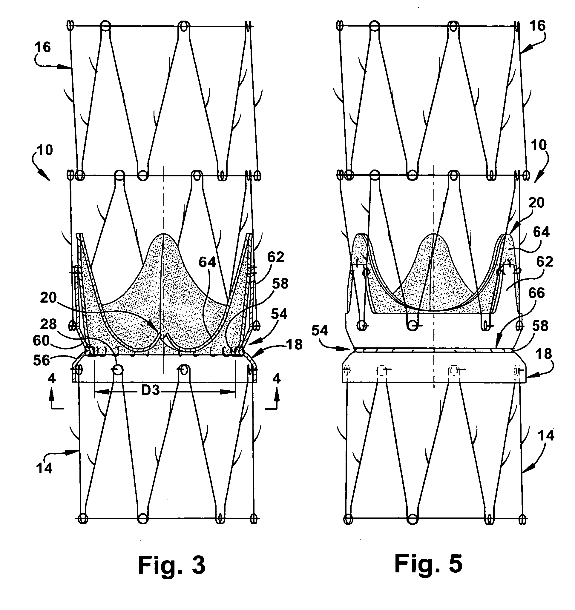
[0046] The present invention is directed to an apparatus and methods for repairing the function of a diseased valve, such as a cardiac or venous valve, via an endovascular technique, and is further directed to methods for making the apparatus. As representative of the present invention, FIGS. 1-4 illustrate an apparatus 10 for repairing the function of a diseased cardiac valve, such as a tricuspid valve 12 shown schematically in FIGS. 6-8. It should be apparent, however, to those skilled in the art that the apparatus 10 disclosed herein can also be used to repair the function of other cardiac valves as well as venous valves. The apparatus 10 includes annular first and second support members 14 and 16, a tubular graft section 18 interconnecting the support members, and a prosthetic valve 20 secured within the graft section.
[0047] The first support member 14 comprises a self-expanding or balloon expandable stent made from stainless steel, but could alternatively be made from any suita...
second embodiment
[0083]FIG. 13 illustrates placement of the apparatus 10b in accordance with the second embodiment to repair the function of a diseased aortic valve. It should be noted that it may be desirable to excise the native aortic leaflets prior to implantation of the apparatus 10b. To enable delivery and deployment of the apparatus, the apparatus 10b is radially collapsed and loaded into a sheath (not shown) over a catheter (not shown). Carotid or subclavian access may be used to cannulate the aorta (AO) and each of the two coronary arteries (CA).
[0084] After de-airing of the assembly, the apparatus 10b is introduced into the aorta. Under fluoroscopic and / or transesophageal echocardiographic guidance, the apparatus 10b is advanced to the desired location above the annulus of the native aortic valve. Wires placed within the coronary arteries may be loaded through guides (not shown) in the conduits 94 and 96 to ensure proper orientation. The sheath is retracted to allow the first and second su...
fifth embodiment
[0096] The primary difference between the apparatus 10e of FIGS. 16-17 and the apparatus 10 of FIGS. 1-4 is that the second end portion 52 of the graft section 18 further includes a plurality of extension stents 62e that extend axially toward the distal end 34 of the second support member 16, in lieu of the extension flaps 62 of the previously described apparatus 10. The extension stents 62e are each connected, such as by sutures, to one of the leaflets 64 of the bioprosthetic valve 20 and may act to support the leaflets 64 in a desired manner. The number and circumferential orientation of the extension stents 62e should correspond to the number and orientation of leaflets 64 in the bioprosthetic valve 20. It is contemplated that the Nitinol ring 66, previously described with regard to FIG. 5, could also be used in FIGS. 16-17 to anchor the extension stents 62e. Conversely, the extension stents 62e could be directly anchored, via sutures or the like, to the second end portion 52 of ...
PUM
 Abstract
Description
Claims
Application Information