Automatic door bottom and sill assemblage

a door bottom and automatic technology, applied in the field of assemblage, can solve the problems of large, more expensive structure, and new water-infiltration problems around the perimeter of the door-bottom device, and achieve the effect of easy trimming to length

Inactive Publication Date: 2006-12-21
BAXTER STEPHEN MARSHALL
View PDF29 Cites 39 Cited by
  • Summary
  • Abstract
  • Description
  • Claims
  • Application Information

AI Technical Summary

Benefits of technology

[0028] Finally, it is an object that the sealing apparatus and the sill be easily trimmed to length without special tools, so that the invention could be used as a retrofit product on its own as well

Problems solved by technology

Commercially available devices may keep out dust and non-conditioned air on a still day, but the seal produced by the relatively weak springs is not nearly strong enough to keep out wind-driven rain.
While a face-mounting device could theoretically be shimmed out beyond the face of the door far enough to work on an inswinging door (the protrusion would mash against the door stop rather than the jamb), this would create new water-infiltration problems around the perimeter of the door-bottom device.
Out-opening doors in such buildings require by code much wider exterior hallways in which to swing and therefore dictate a bigger, more expensive structure.
Also, outswinging doors are awkward and more subject to catching in th

Method used


Image

  • Automatic door bottom and sill assemblage
  • Automatic door bottom and sill assemblage
  • Automatic door bottom and sill assemblage

Examples


Embodiment Construction

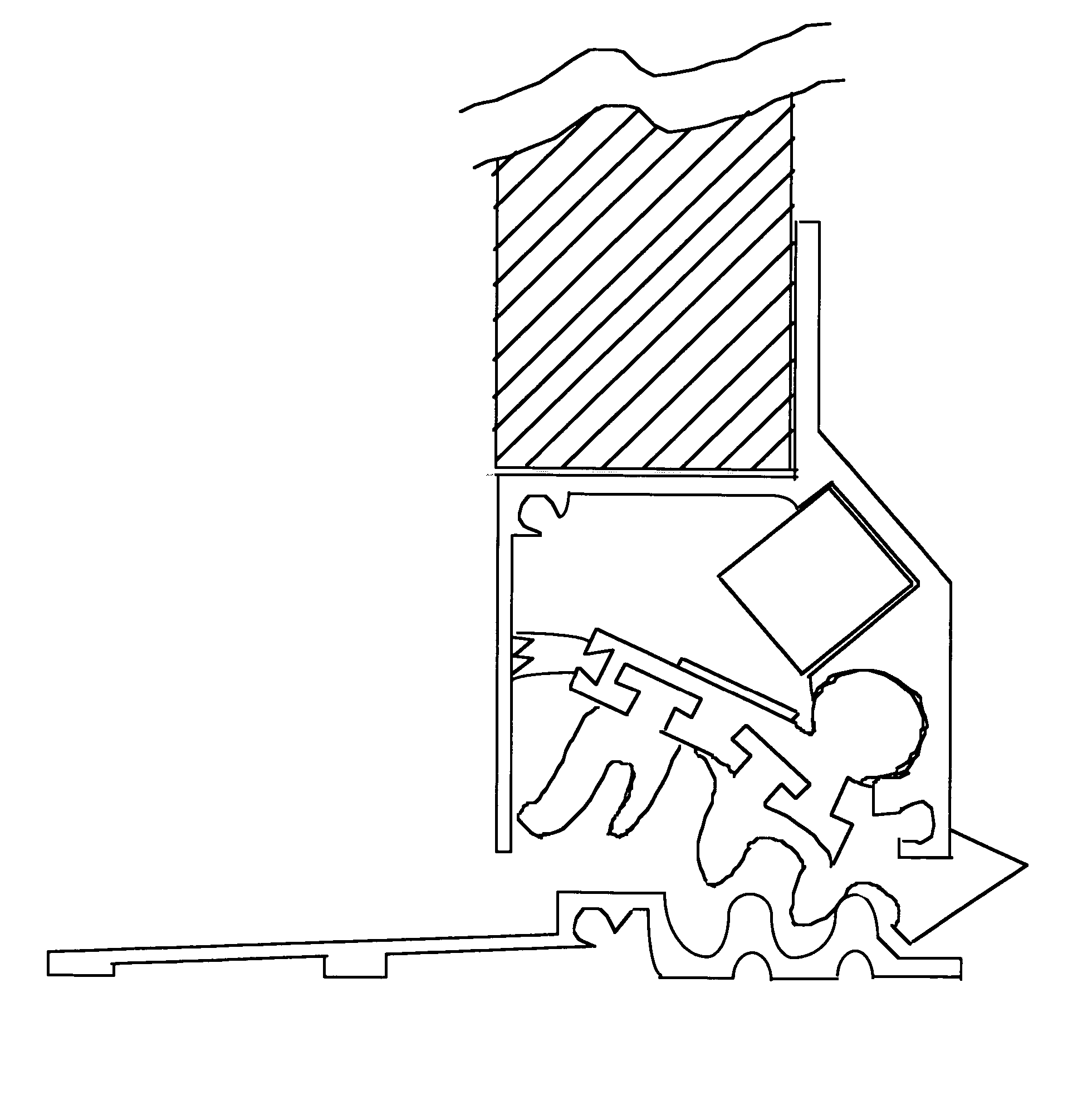
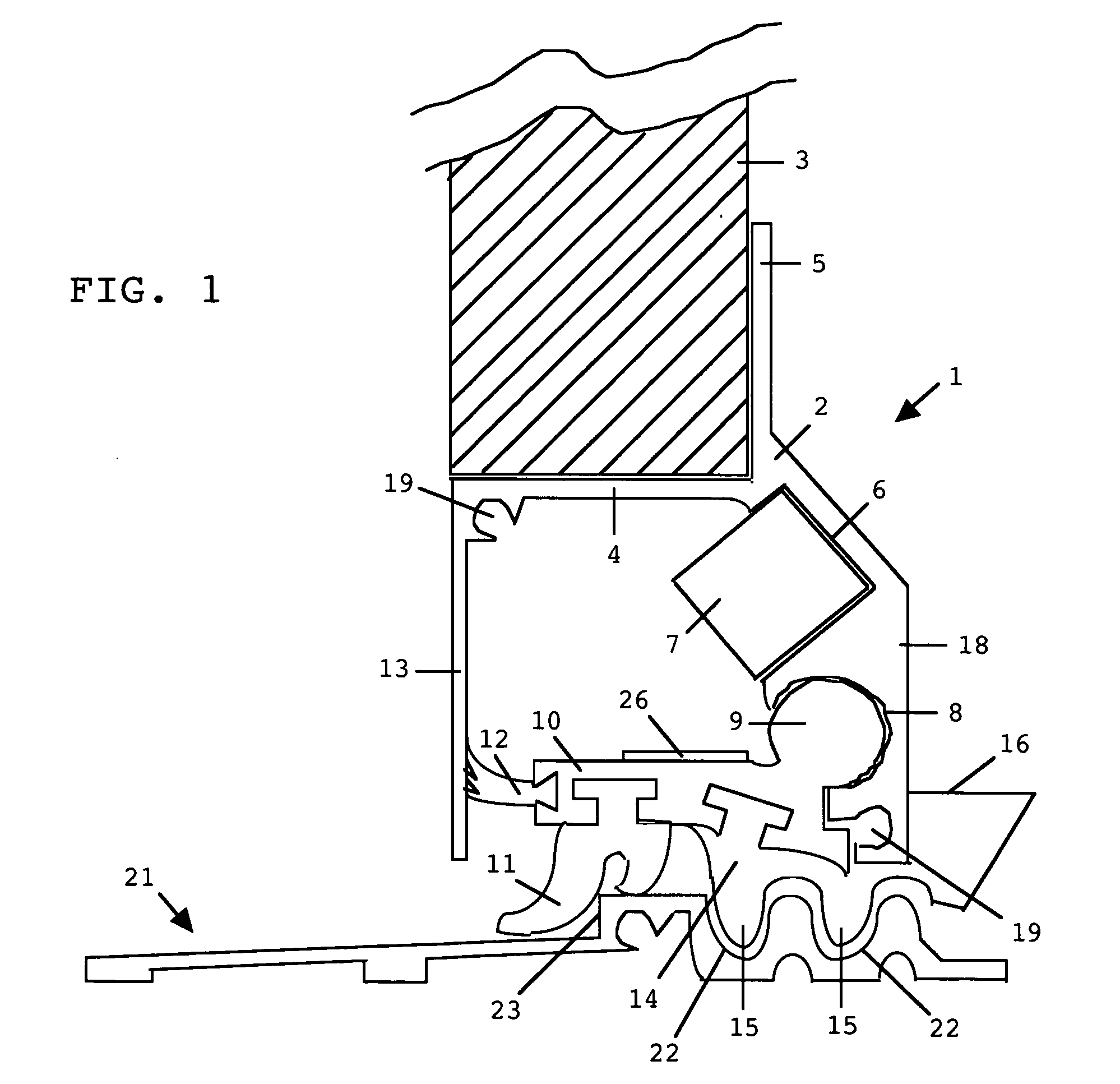
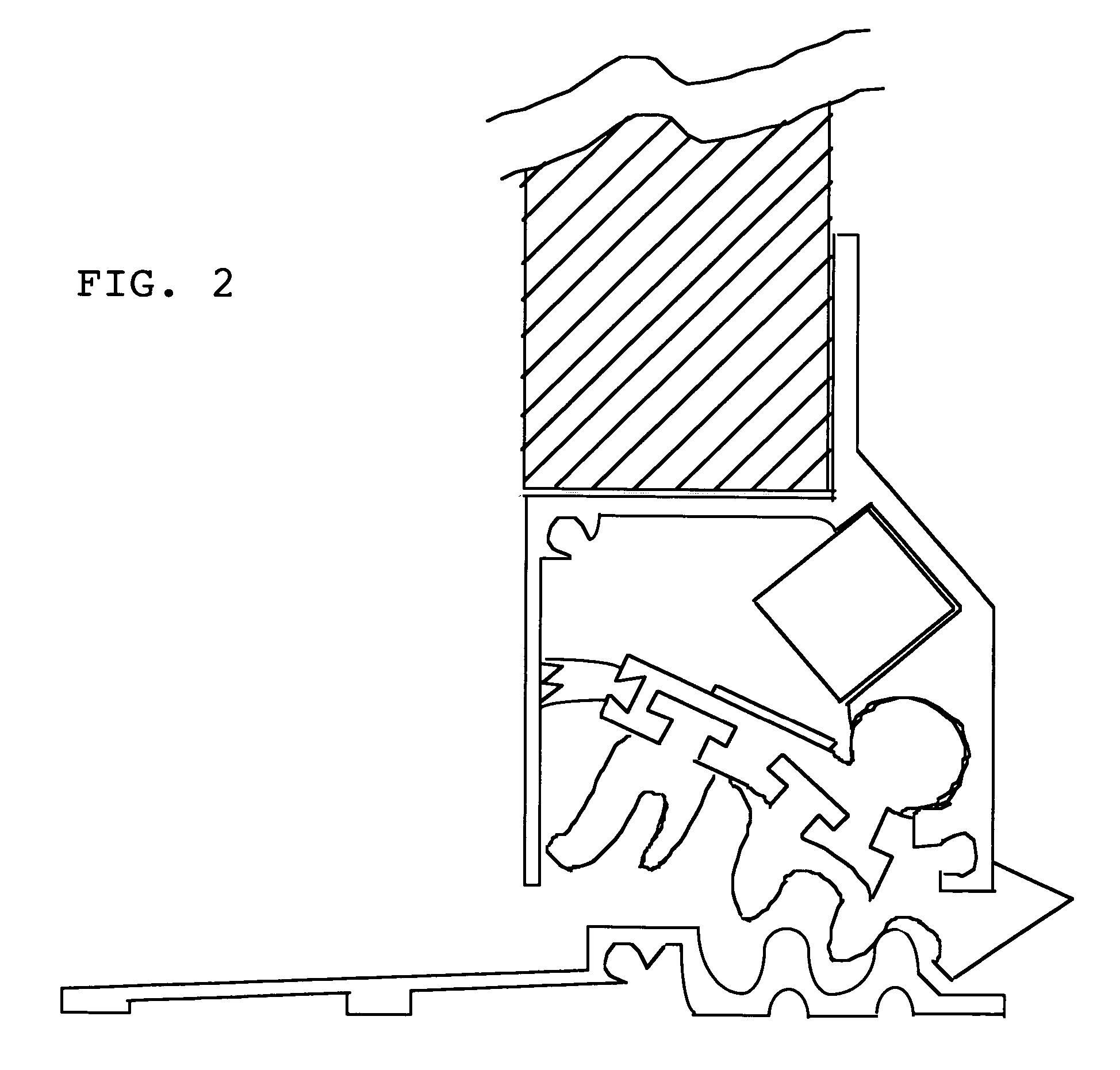
[0036] The detailed embodiments of the invention disclosed herein are merely exemplary of the invention which may be embodied in other forms, and therefore are not intended to be limiting in nature. Reference numbers of parts are shown in FIG. 1 and FIG. 4, but not in FIG. 2 and FIG. 3., since the viewable parts in the latter are exactly the same as those in FIG. 1.

[0037] The sealing mechanism 1 consists of a generally inverted h-shaped housing 2 which is fastened to the bottom of—and runs the width of—an exterior door 3. (The fasteners, not shown, could pass into the door 3 through the horizontal part 4 of the housing 2 and / or through the flange 5 located on the interior side of the door 3.)

[0038] Integral to the housing 2 are an elongated recess 6 for accommodating a generally square magnet 7 at any point along its width and a tubular recess 8, open on one side, containing a separate rotating cylindrical shaft 9 with an arm extension 10 to the underside of which is fastened a fl...


PUM

PropertyMeasurementUnit
Electrical resistanceaaaaaaaaaa
Flexibilityaaaaaaaaaa

Abstract

A door sill and a sealing mechanism engage one another analogously to a rack and pinion in order to automatically create a weather-resistant closure at the gap between an inswinging exterior door bottom and the floor below. The sealing mechanism, which fastens to the door bottom, contains a door-wide rotating shaft with an arm extension tipped with a flexible seal. On the underside of the shaft extension is a short “pinion” component with elongated teeth that engage in corresponding recesses in the sill, raising and lowering the seal in the process. The pinion is positioned on the far lock side of the door, so that the teeth engage and the seal begins to drop only when the door is nearly closed. As the door opens and the seal rises, a magnet further retracts the shaft extension and retains it until the door is again closed.

Description

CROSS-REFERENCE TO RELATED APPLICATIONS [0001] This application succeeds Provisional Patent Application 60 / 692,351. That provisional application was filed Jun. 21, 2005 under the title “Weather-Resistant Door-Floor Interface Assembly.”BACKGROUND OF THE INVENTION [0002] 1. Field of the Invention [0003] The invention is an “assemblage” in that it consists of two main components: a retractable door seal attached to the underside of an inswinging door and a floor sill against which it tightly presses. The movement of the seal down towards the sill is actuated by the closure of the door itself. [0004] The design of fenestration products must meet architectural needs but also satisfy various government regulations that sometimes work at odds to one another. Post-Hurricane Andrew building codes require ever tighter closure of such products against very high onslaughts of wind and rain. But other regulations make that job more difficult. The American with Disabilities Act, for example, limi...

Claims


Application Information

Patent Timeline
IPC IPC(8): E06B7/20
CPCE06B7/2316E06B7/20
Inventor BAXTER, STEPHEN MARSHALL
Owner BAXTER STEPHEN MARSHALL
Why Eureka
Try Eureka