Anti-vibration locking device for pipe and cable clamps

a technology of anti-vibration locking and pipe and cable clamping, which is applied in the field of improvement, can solve the problems of accelerating the failure applying different forces or torques, and affecting the operation of the clamping system,

Inactive Publication Date: 2006-12-21
THOMAS & BETTS INT INC
View PDF22 Cites 23 Cited by
  • Summary
  • Abstract
  • Description
  • Claims
  • Application Information

AI Technical Summary

Problems solved by technology

However, when using clamps that employ threaded bolts, it becomes readily apparent that different installers apply different forces or torque when compressing the pipe between the saddle and the structural member.
Thus, if too much torque is applied by the installer, the pipe and clamp are over-pressurized and thus subject to deformation or breakage.
Such a situation will result in even greater pipe vibration or movement at adjacent clamp locations thereby subjecting these adjacent clamps to the same, if not greater, debilita

Method used


Image

  • Anti-vibration locking device for pipe and cable clamps
  • Anti-vibration locking device for pipe and cable clamps
  • Anti-vibration locking device for pipe and cable clamps

Examples


Embodiment Construction

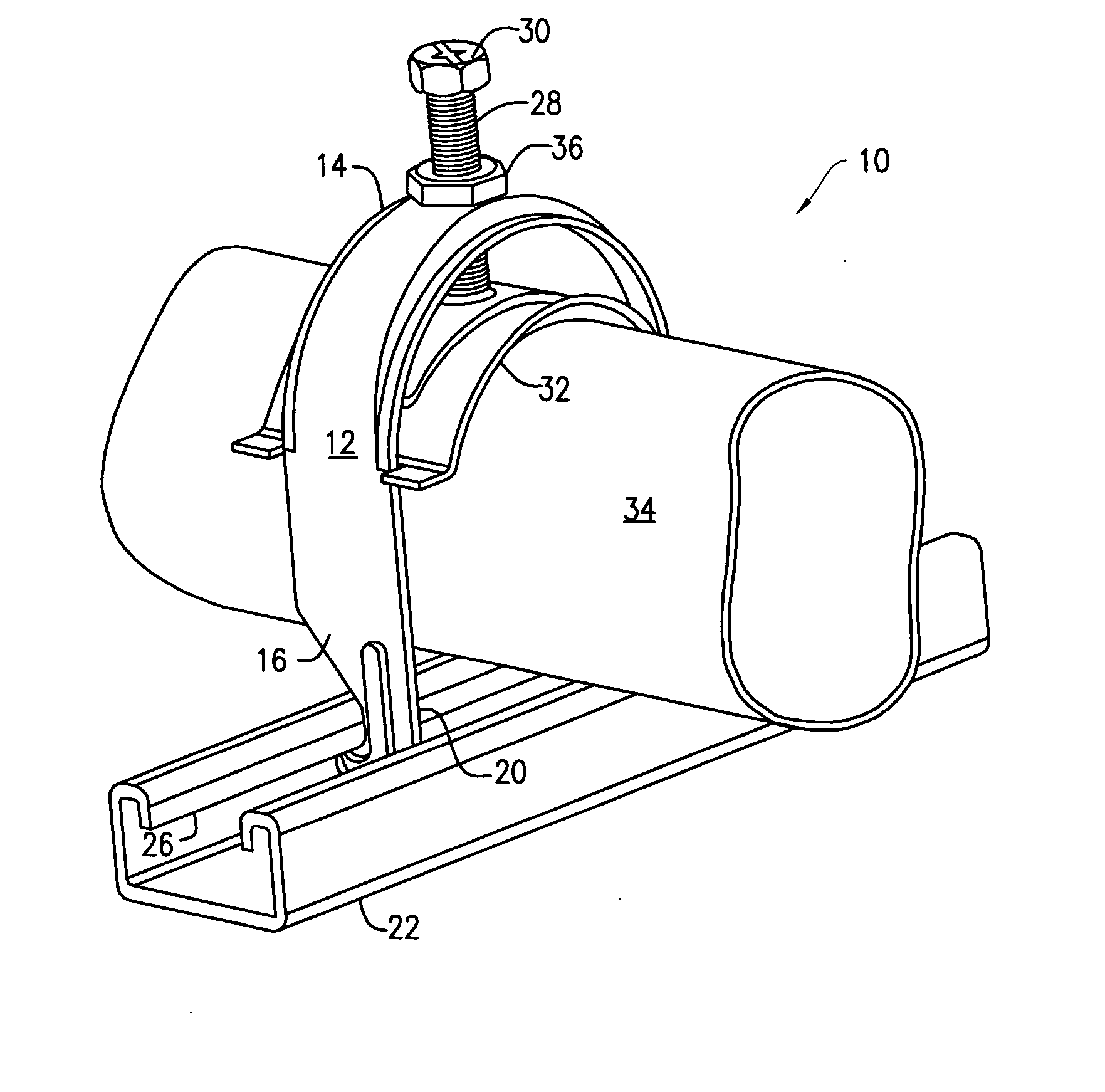
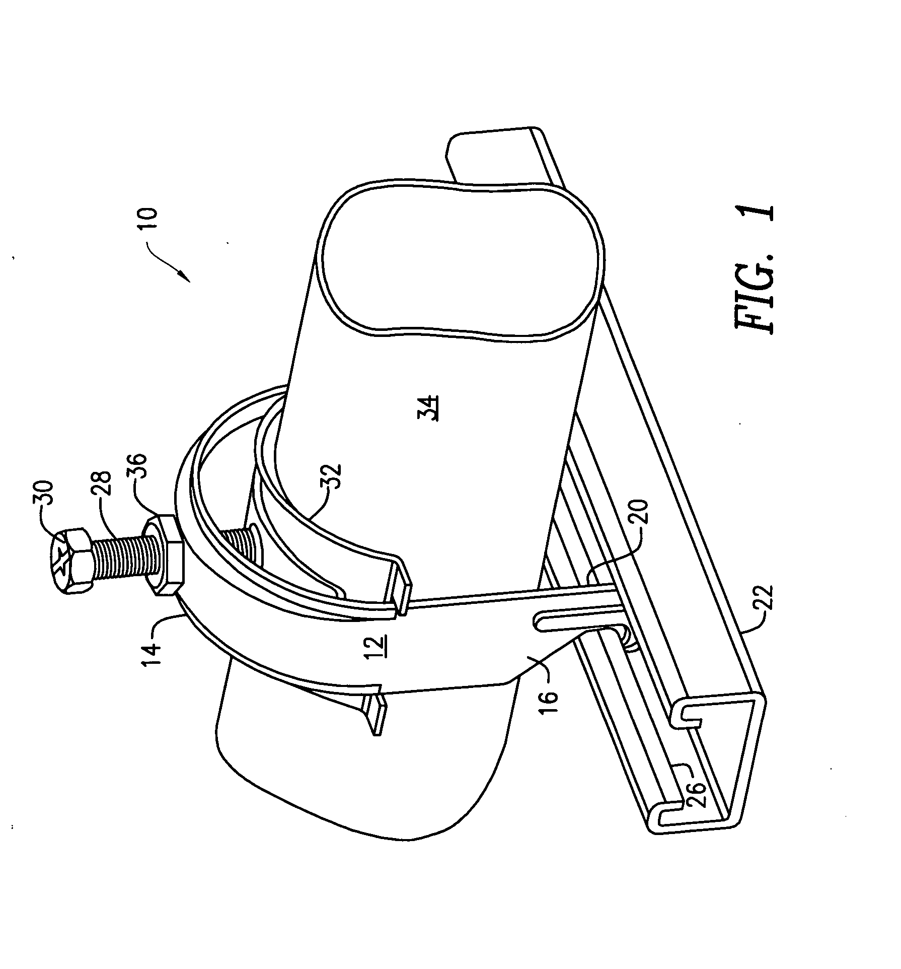
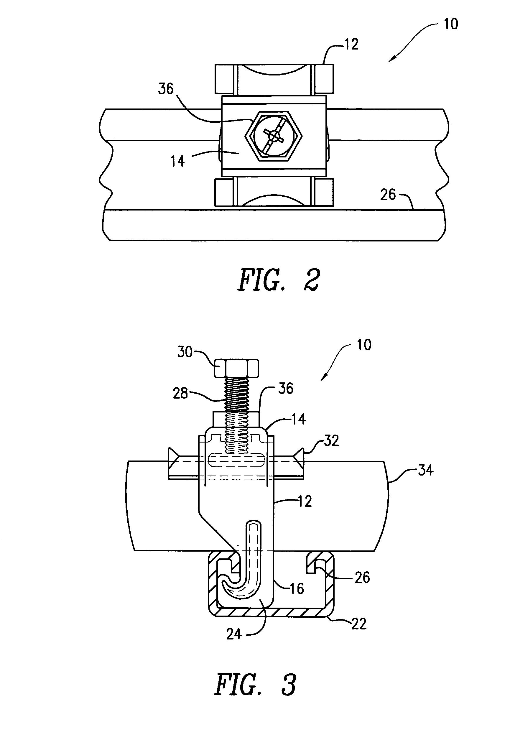
[0020] Referring initially to FIG. 1, there is a shown a pipe clamp 10 of typical construction incorporating an inverted U-shaped clamp body 12 having a transverse surface 14 and a pair of spaced-apart legs 16 depending therefrom. Intermediate legs 16 is pipe receiving location 18 while the distal end region 20 of each leg 16 is configured for attachment to a structural member 22, such as a strut as shown. In this regard, distal end region 20 may include hook-like ends 24 which are engageable with lip 26 of a conventional U-shaped strut 22. As shown, bolt 28 passes through a threaded opening in transverse surface 14 in the conventional fashion. One end region of bolt 28 is configured with a head 30 while a pipe engaging saddle 32 is affixed to the opposite end region. Obviously, as bolt 28 is rotated, saddle 32 is raised or lowered with respect to transverse surface 14. It is to be understood that the foregoing arrangement and / or construction may vary depending on the particular pip...


PUM


Abstract

The present invention provides a clamp body having a transverse surface and a threaded opening therein, a threaded bolt threaded through the opening, the bolt having a head at one end region and a saddle at an opposite end region, the saddle configured to clamp against a pipe, a locknut threaded on the bolt, the locknut adapted to being rotated on the bolt against the head with a predetermined amount of torque, the predetermined amount corresponding with a pre-determined force to be applied by the saddle against the pipe.

Description

CROSS-REFERENCE TO RELATED APPLICATIONS [0001] This application claims the benefit of U.S. Provisional Application No. 60 / 668,133 filed on Apr. 4, 2005, entitled “Anti-Vibration Locking Device for Pipe and Cable Clamps”.FIELD OF THE INVENTION [0002] This invention pertains to an improved pipe and cable clamp for more efficiently and effectively securing a pipe, cable or conduit to a support structure. The present invention provides a locknut and bolt clamping system wherein a predetermined bias is imparted by the clamp and wherein the clamp is also designed to maintain this optimal pressure against the pipe, clamp or conduit. Such features are especially important with jacketed cables where the jacket could be pierced or damaged if over-tightened, thereby compromising the integrity of the cable. BACKGROUND OF THE INVENTION [0003] The use of pipe clamps to attach or fasten pipes or conduit to support structures is well known in the art. Such clamps typically include a saddle affixed ...

Claims


Application Information

Patent Timeline
IPC IPC(8): F16L3/08
CPCF16L3/04F16L55/035F16L3/24F16L3/1211F16L3/243
Inventor SMITH, WILLIAM J.MICHAUD, ALAINLALANCETTE, DANIEL
Owner THOMAS & BETTS INT INC
Why Eureka
Try Eureka