Method and device for using compressed gas as a weapon

a technology of compressed gas and weapon, which is applied in fishing, manufacturing tools, and portable power-driven tools, etc., can solve the problems of less effective disabling effect of gas, more aggressive behavior, and single function of compressed gas stilettos of the prior art, and achieve the effect of enhancing the incapacitating effect of the kni

Active Publication Date: 2006-12-28
JASPER COMPANY THE
View PDF11 Cites 4 Cited by
  • Summary
  • Abstract
  • Description
  • Claims
  • Application Information

AI Technical Summary

Benefits of technology

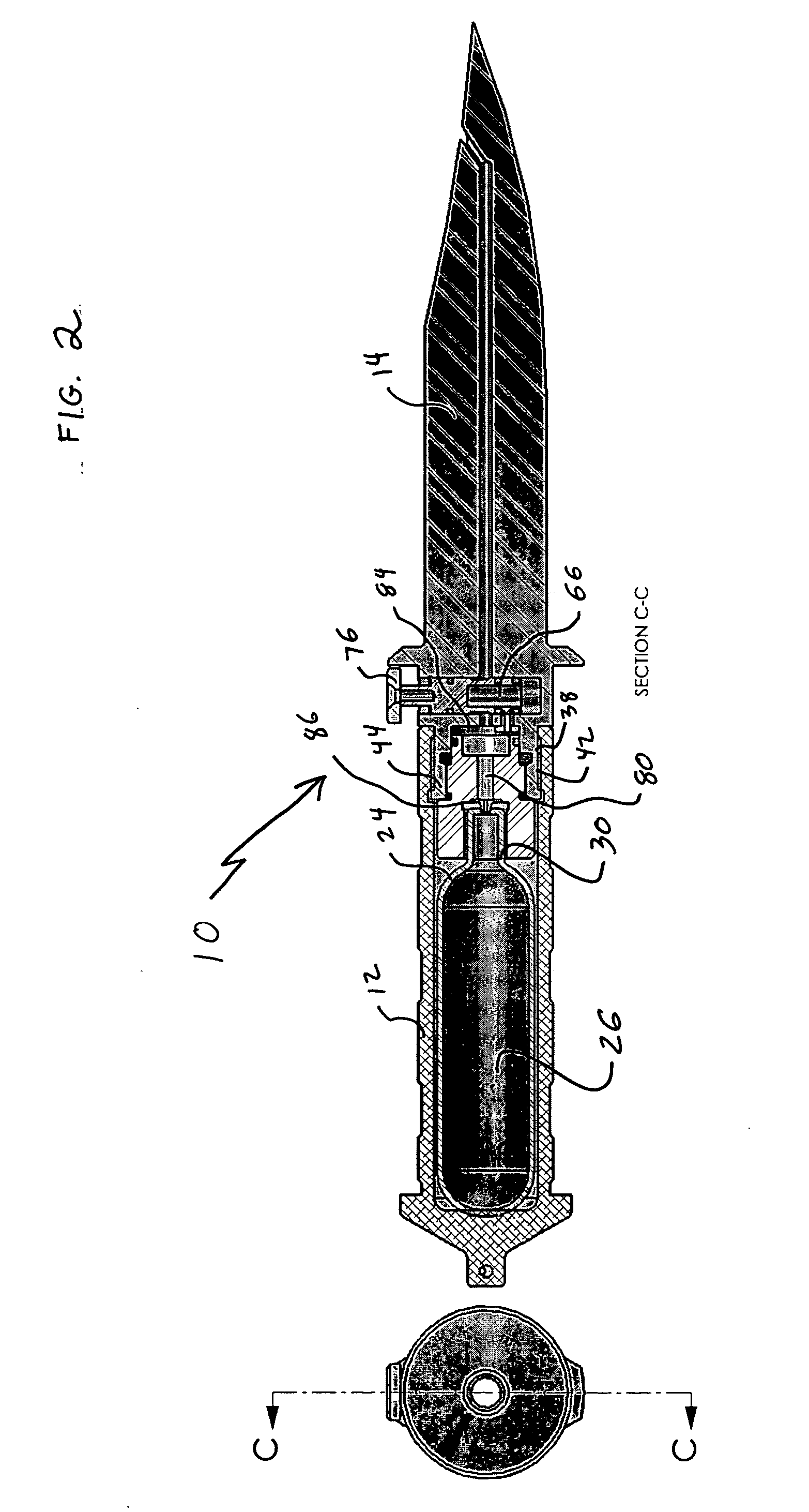
[0011] In accordance with the invention, there is provided a knife includes a handle, a blade and a trigger. The handle has an internal cavity containing a compressed gas source and the blade is affixed to the handle. The blade has an internal bore running along a longitudinal axis from the handle to a point proximate a tip. The blade further has an aperture extending from a first edge to the internal bore at an angle relative to the longitudinal axis of between 15° and 75°. The trigger has a depressed position and a not depressed position. When in the depressed position, the internal bore communicates with the compressed gas source and when in said not depressed position, the internal bore is blocked from the compressed gas source. When a creature is pierced with the knife, the trigger is depressed injecting compressed gas into the creature greatly enhancing the incapacitating effect of the knife.
[0012] It is a feature of the invention that the knife is particularly useful for a diver and that when an undersea creature is pierced, the compressed gas both causes tissue and organ damage and provides buoyancy to float the creature towards the surface.

Problems solved by technology

However, stabbing a large undersea animal, such as a shark, usually infuriates the animal causing more aggressive behavior.
The compressed gas stilettos of the prior art have a single function and are not utilitarian.
Further, the transverse through hole of the compressed gas stiletto expels the compressed gas close to the surface of the pierced creature where the disabling effects of the gas are less effective.

Method used


Image

  • Method and device for using compressed gas as a weapon
  • Method and device for using compressed gas as a weapon
  • Method and device for using compressed gas as a weapon

Examples


Embodiment Construction

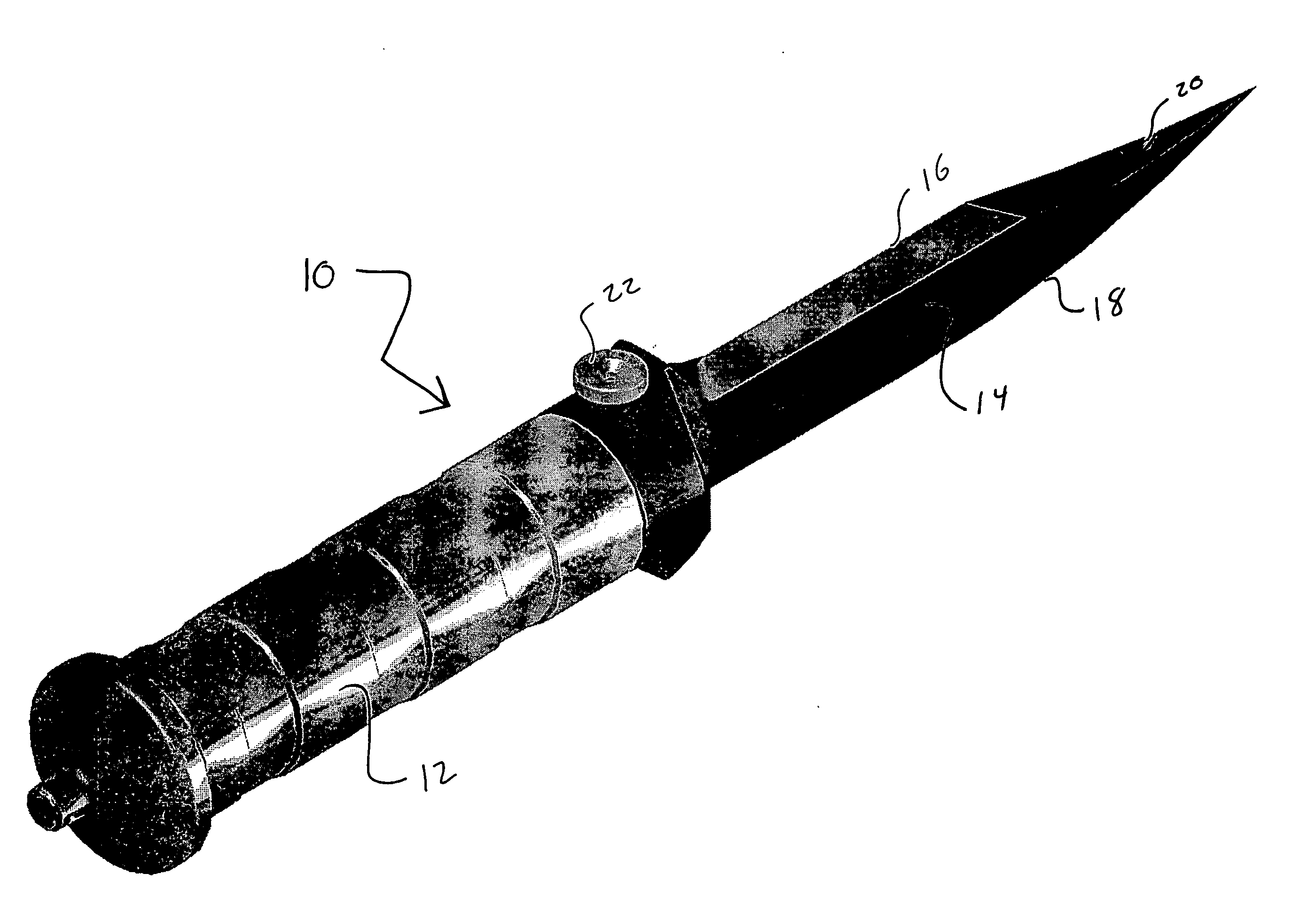
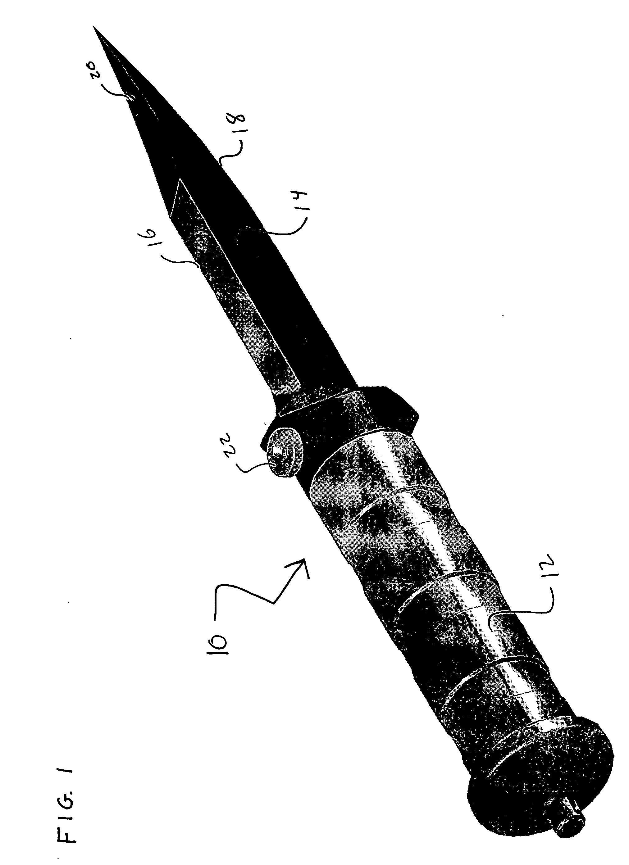
[0022]FIG. 1 illustrates an undersea weapon 10 having a handle 12 and knife blade 14. The knife blade has at least a first cutting surface 16 and, preferably, also has a second cutting surface 18. As such, the undersea weapon 10 is useful for use by a diver to cut ropes, vegetation and other objects. An aperture 20 extends to the first cutting surface 16 at an angle to a longitudinal axis of the undersea weapon. A trigger 22 is disposed between the handle 12 and knife blade 14. When the trigger is depressed, a compressed gas contained within the handle is released via aperture 20. If the knife blade 14 has pierced an undersea creature, the compressed gas is injected into the creature causing damage to the creature's tissue and organs, thereby disabling it. The gas also increases the buoyancy of the creature causing it to rise toward the surface and suffer severe overexpansion damage by rapid expansion of the gas due to the release of ambient pressure as the creature rises to the sur...


PUM

PropertyMeasurementUnit
angleaaaaaaaaaa
angleaaaaaaaaaa
angleaaaaaaaaaa

Abstract

A knife includes a handle, a blade and a trigger. The handle has an internal cavity containing a compressed gas source and the blade is affixed to the handle. The blade has an internal bore running along a longitudinal axis from the handle to a point proximate a tip. The blade further has an aperture extending from a first edge to the internal bore at an angle relative to the longitudinal axis of between 15° and 75°. The trigger has a depressed position and a not depressed position. When in the depressed position, the internal bore communicates with the compressed gas source and when in said not depressed position, the internal bore is blocked from the compressed gas source. When a creature is pierced with the knife, the trigger is depressed injecting compressed gas into the creature greatly enhancing the incapacitating effect of the knife.

Description

CROSS REFERENCE TO RELATED APPLICATION(S) [0001] This patent application is a continuation-in-part of commonly owned U.S. patent application Ser. No. 11 / 166,729 entitled “Method and Device for Using Compressed Gas as a Weapon” that was filed on Jun. 27, 2005. Patent application Ser. No. 11 / 166,729 is incorporated by reference in its entirety herein.U.S. GOVERNMENT RIGHTS [0002] N.A. BACKGROUND OF THE INVENTION [0003] 1. Field of the Invention [0004] This invention relates to a device to protect divers from undersea creatures, and more particularly to a utilitarian knife having a bore extending within the blade from a compressed gas source to an edge of the knife. After a creature is pierced, the diver actuates a trigger releasing compressed gas to travel through the bore and into the creature, thereby instantly disabling it. [0005] 2. Description of the Related Art [0006] Experienced divers recognize that the undersea world is one of great mystery, beauty and history, but also poten...

Claims


Application Information

Patent Timeline
Patent Type & Authority Applications(United States)
IPC IPC(8): B26B3/00B26B11/00
CPCA22B3/10F41B11/62B26B11/00B26B3/00Y10T83/04
Inventor RONDINONE, GREGORY T.
Owner JASPER COMPANY THE
Why Eureka
Try Eureka