
Rod reducer

a technology of rod reducer and reducer, which is applied in the field of medical devices, can solve the problems of not being able to achieve minimally invasive surgery, not being able to effectively operate with two hands, and being bulky

Active Publication Date: 2006-12-28
CUSTOM SPINE INC
View PDF24 Cites 45 Cited by
  • Summary
  • Abstract
  • Description
  • Claims
  • Application Information

AI Technical Summary

Problems solved by technology

Most conventional rod reducers are typically bulky and / or require two hands to properly operate.
Furthermore, the conventional solutions are generally bereft of a viable solution for rod reduction when L5-S1 implants are very close together or touching to reduce spondylothesis during spinal deformity surgeries.
As such, most conventional rod reducers tend to suffer from the following attributes: (1) they are generally too bulky and not minimally invasive surgery (MIS) compatible; (2) they generally require two handed operation; (3) they typically require too much space in the medial or lateral direction and interfere with the facet or the transverse process; and (4) they tend to apply too much force through a threaded mechanism, which does not allow for tactile sensation.
This could result in the possibility of the bone anchor in a pedicle screw assembly being pulled out of the anatomy during operation.

Method used


Image

  • Rod reducer
  • Rod reducer
  • Rod reducer

Examples


Embodiment Construction

[0017] The embodiments of the invention and the various features and advantageous details thereof are explained more fully with reference to the non-limiting embodiments that are illustrated in the accompanying drawings and detailed in the following description. It should be noted that the features illustrated in the drawings are not necessarily drawn to scale. Descriptions of well-known components and processing techniques are omitted so as to not unnecessarily obscure the embodiments of the invention. The examples used herein are intended merely to facilitate an understanding of ways in which the embodiments of the invention may be practiced and to further enable those of skill in the art to practice the embodiments of the invention. Accordingly, the examples should not be construed as limiting the scope of the embodiments of the invention.

[0018] As mentioned, there remains a need for a novel rod reducer device capable of reducing spondylothesis during spinal deformity surgeries,...


PUM


Abstract

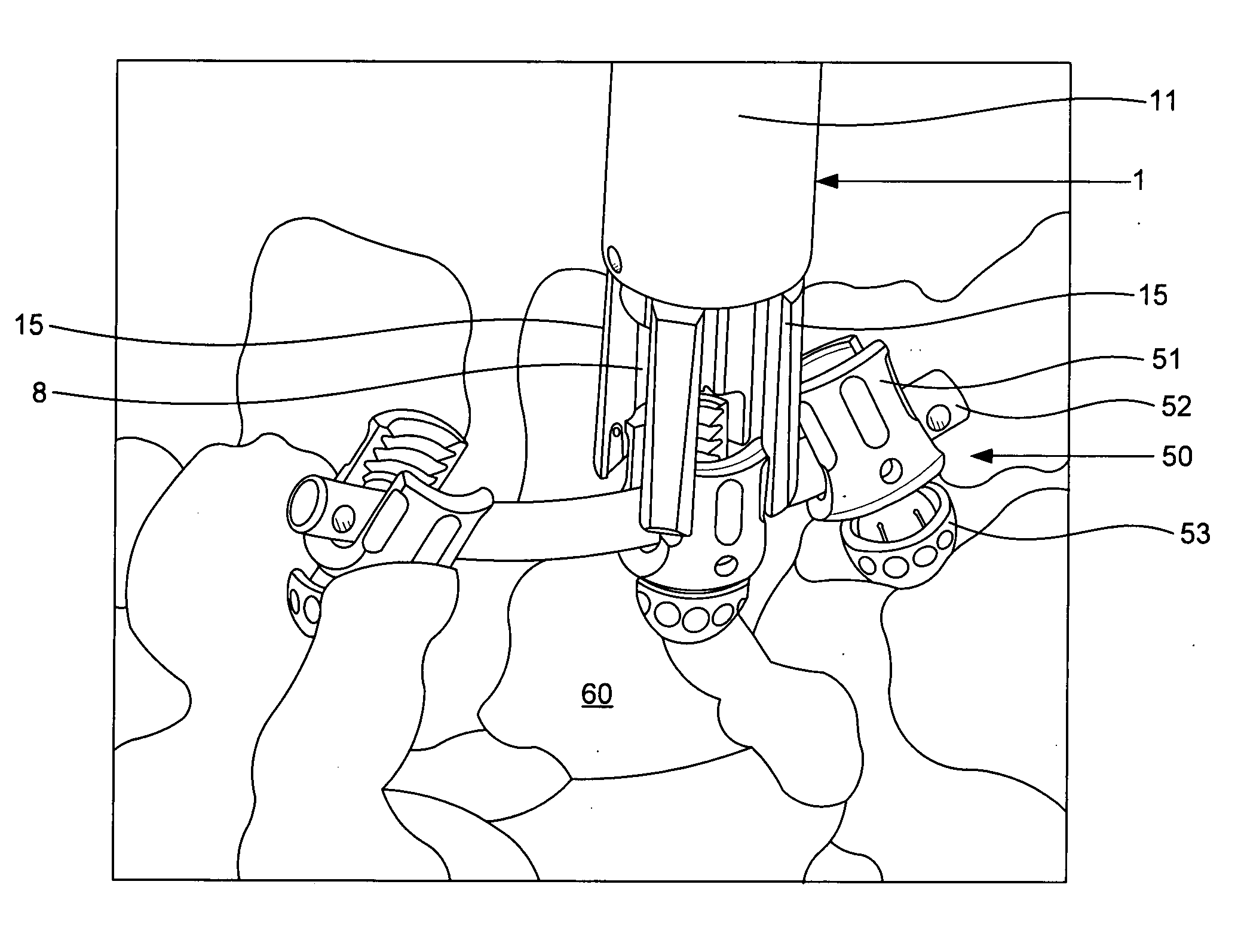
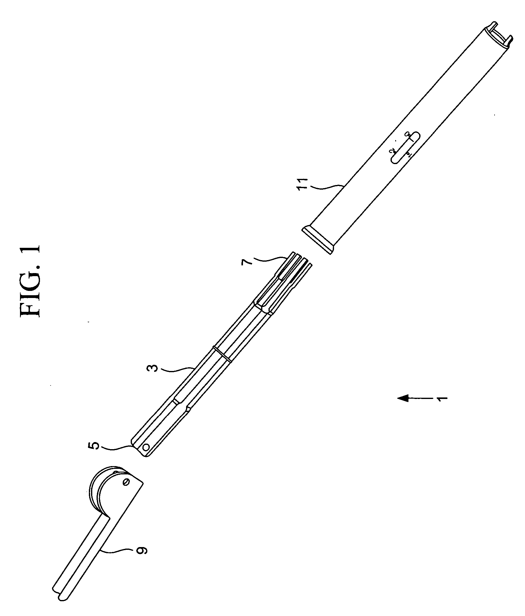
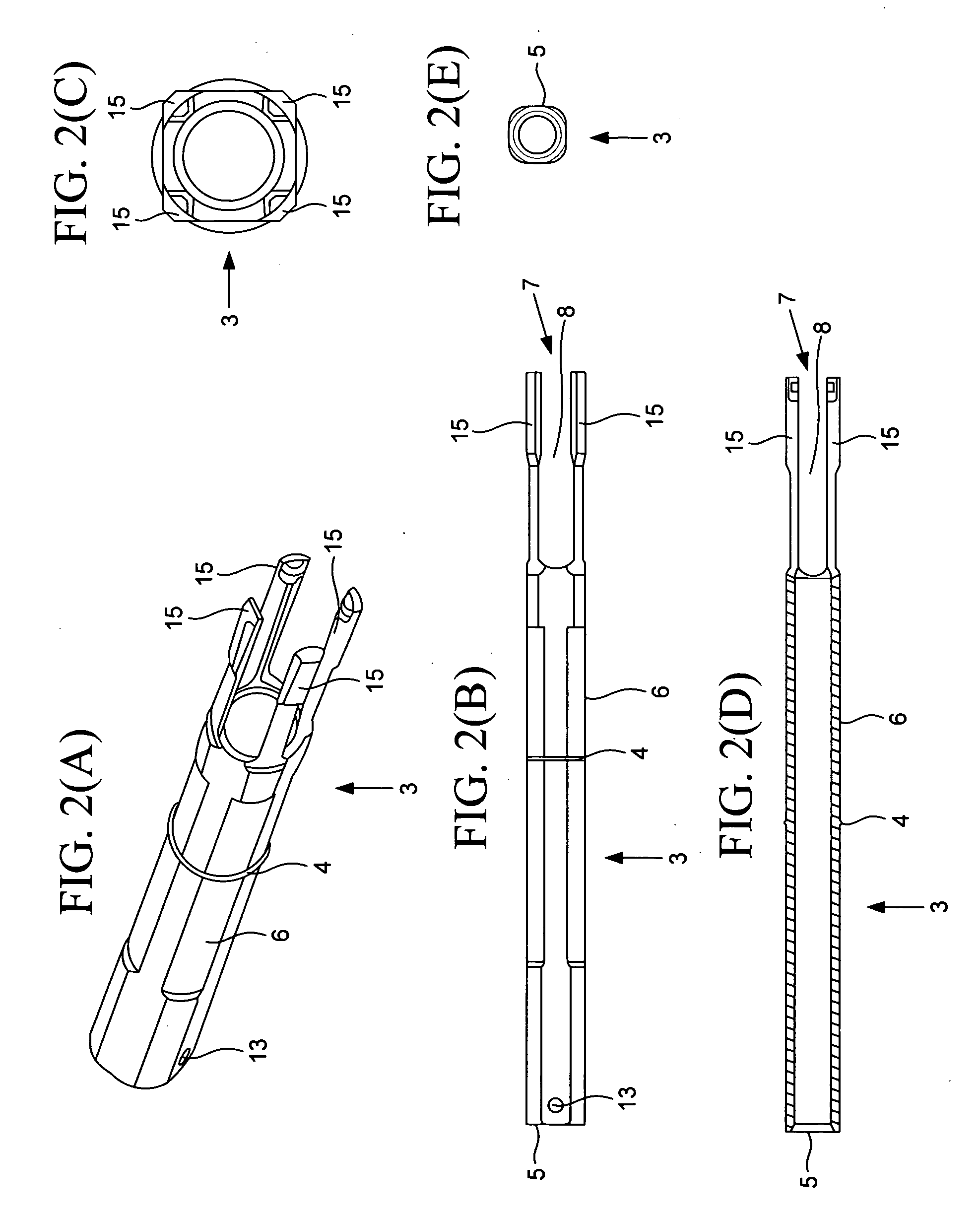
A cam coupling rod reducer and method of operation comprises an inner tube comprising a first end having a hole and a second end having a plurality of prongs extending therefrom. The rod reducer further includes a lever cam connected to the first end, wherein the lever cam comprises a base and a pair of semicircular arms extending from the base, wherein each of the arms comprise a hole configured to align with the hole of the first end of the inner tube. The rod reducer also includes an outer extension tube connected to the inner tube, wherein the outer extension tube comprises positional markings on the body of the outer extension tube; a top end having a concave opening; and a bottom end comprising an opening configured to permit the prongs of the inner tube to extend therethrough; and a pair of pegs extending from the bottom end.

Description

CROSS REFERENCE TO RELATED APPLICATION [0001] This application claims the benefit of U.S. Provisional Patent Application No. 60 / 683,697 filed on May 23, 2005, the contents of which in its entirety is herein incorporated by reference.BACKGROUND [0002] 1. Field of the Invention [0003] The embodiments of the invention generally relate to medical devices, and, more particularly, to medical devices for use in spinal surgeries. [0004] 2. Description of the Related Art [0005] Most conventional rod reducers are typically bulky and / or require two hands to properly operate. Furthermore, the conventional solutions are generally bereft of a viable solution for rod reduction when L5-S1 implants are very close together or touching to reduce spondylothesis during spinal deformity surgeries. As such, most conventional rod reducers tend to suffer from the following attributes: (1) they are generally too bulky and not minimally invasive surgery (MIS) compatible; (2) they generally require two handed ...

Claims


Application Information

Patent Timeline
IPC IPC(8): A61B17/58
CPCA61B17/7086Y10S606/914
Inventor ABDELGANY, MAHMOUD F.
Owner CUSTOM SPINE INC
Learn More