
Meter-base surge protector
a surge protector and meter-base technology, applied in the direction of overvoltage protection resistors, emergency protective arrangements for limiting excess voltage/current, and arrangements responsive to excess voltage, can solve the problems of interruption of surge protection and is currently not available, and achieve high-speed broadband data transmission and reduce capacitan
- Summary
- Abstract
- Description
- Claims
- Application Information
AI Technical Summary
Benefits of technology
Problems solved by technology
Method used
Image

Examples
Embodiment Construction
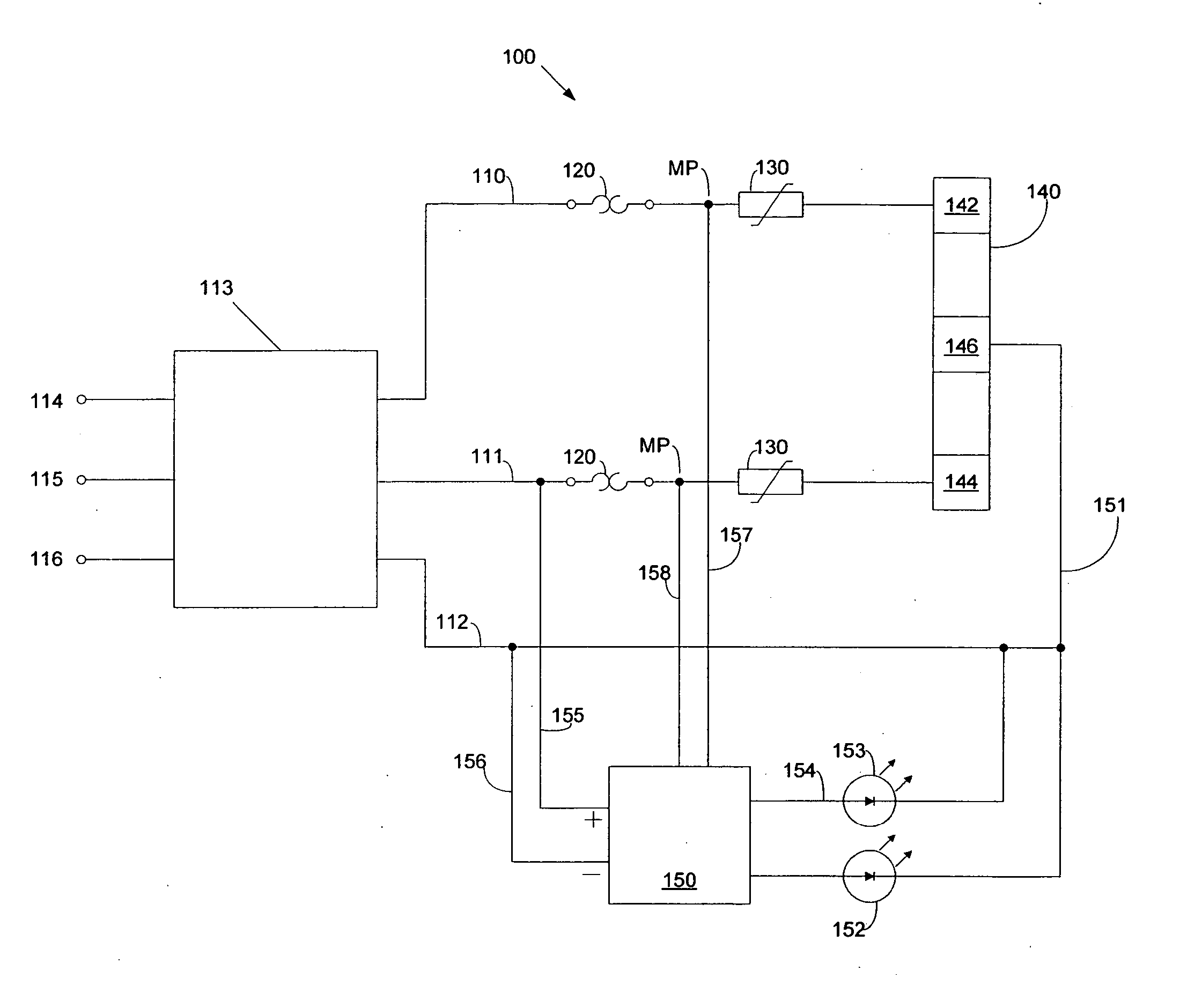
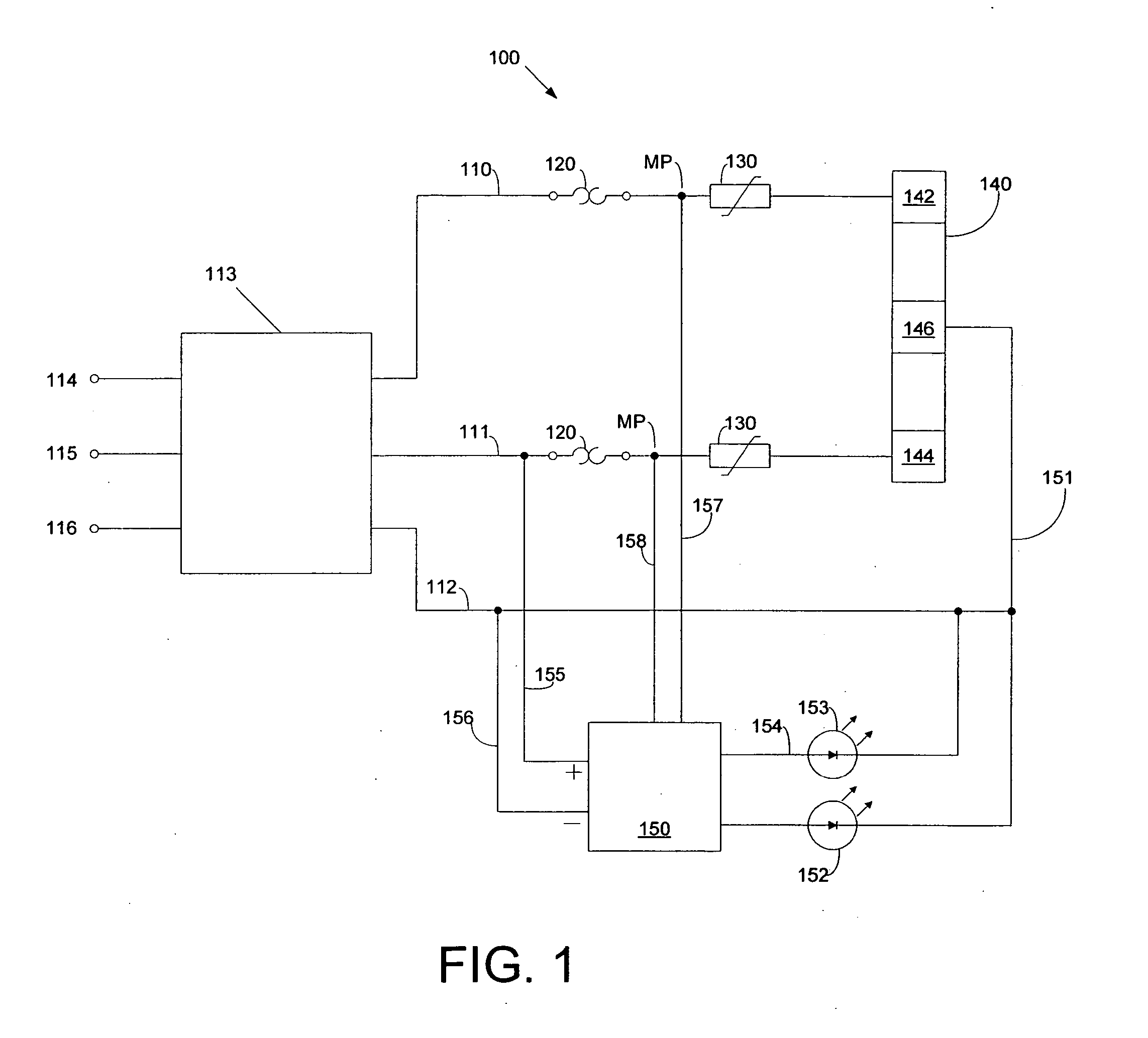
[0019]FIG. 1 is a schematic diagram of surge protector circuit 100 of the present invention. Surge protector circuit 100 includes conductors 110, 111, and 112 that are respectively adapted to be connected, via building power meter 113, to AC power line 114, AC power line 115, and neutral line 116. Conductor 110 is connected to first TCO 120, which is connected in series with first MOV 130 and first electrode 142 of three-electrode GDT 140. Conductor 111 is likewise connected to second TCO 120, which is connected in series with second MOV 130 and second electrode 144 of three-electrode GDT 140. Any arrangement and number of AC power lines, conductors, MOVs, TCOs, electrodes and GDTs may be utilized in the invention in order to achieve the functions and advantages stated herein.
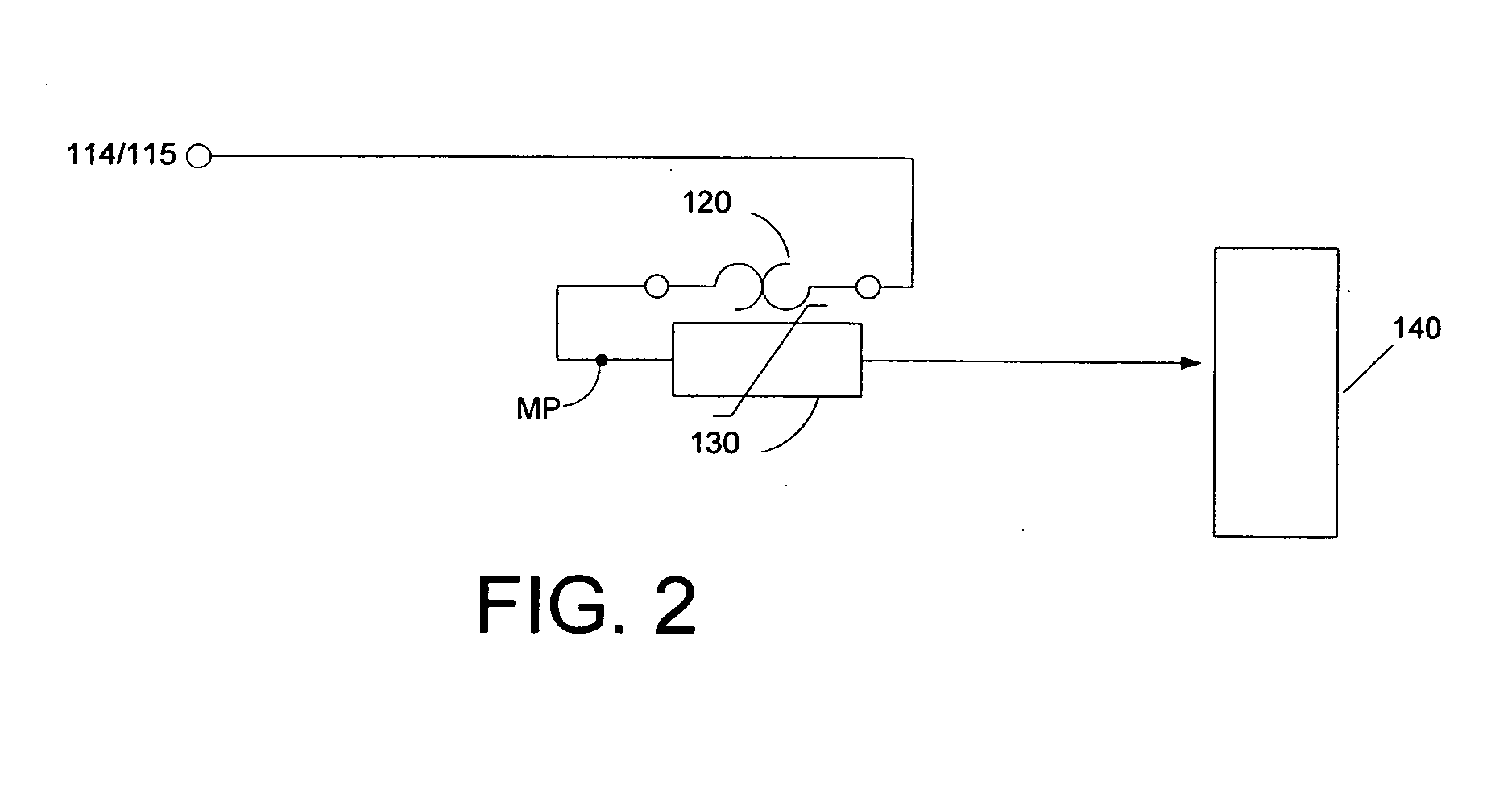
[0020] As shown in FIG. 2, the TCOs and MOVs are physically positioned in proximity, or physical contact, with one another so as to allow heat generated and dissipated by for example MOV 130 to be distributed ...
PUM
 Abstract
Description
Claims
Application Information