Micromechanical optical element having a reflective surface as well as its use

a micromechanical and optical element technology, applied in the field of micromechanical optical elements having a reflective surface, can solve the problems of undesirable influence on the reflection behaviour, need to increase at least the force, and the reflective surface deformation, so as to achieve a significant reduction of the overall torque and the dynamic deformation

Active Publication Date: 2007-01-25
FRAUNHOFER GESELLSCHAFT ZUR FOERDERUNG DER ANGEWANDTEN FORSCHUNG EV
View PDF13 Cites 34 Cited by
  • Summary
  • Abstract
  • Description
  • Claims
  • Application Information

AI Technical Summary

Benefits of technology

[0013] However, spring elements can also act on stiffening elements which are formed on the rear face of the elements which can be deflected, so that the respective advantageous effects can be used in combination.
[0014] The spring element choice is not restricted to torsion springs and, very particularly, not to torsion bar springs. Pure bending springs and torsion bending springs may also be used on their own or in combination.
[0015] Taking account of the respective lever ratios, that is to say the respective distances between the points of action of spring elements on the element which can be deflected, the individual spring elements may also have different, appropriately matched, spring constants.
[0016] However, in one alternative, all of the points of action may also be arranged such that no point of action of a spring element is arranged on the rotation axis.
[0017] The local distribution which can be achieved according to the invention of the forces and torques which the spring elements cause to act on the element which can be deflected allow the overall torque and the dynamic deformation to be considerably reduced, in particular in conjunction with the matching of the spring constants or spring stiffnesses of the spring elements which are used.
[0018] In addition, it has been found that, in the case of an element according to the invention, spring elements which are connected on the rotation axis make only a minor contribution to the overall restoring torque. It is thus also possible to dispense with an embodiment such as this, and points of action of spring elements should then be chosen at shorter distances from the rotation axis.

Problems solved by technology

Since the deflected elements are normally in the form of plates with a different circumferential geometry, their moment of inertia and the limited strength and stiffness lead to dynamic deformation, which in turn leads to deformation of the reflective surface.
With the conventional design of the elements to be deflected, however, even deformation in the nanometer range leads to an undesirable influence on the reflection behaviour.
However, increase in the mass results here, hence the need to increase at least the forces which are required for deflection.
This involves a considerable amount of manufacturing effort, since these spring elements must be designed to be very small.
It is thus likewise impossible to specifically compensate for forces and torques which have locally different effects because of the moment of inertia, in particular the restoring forces and torques which are initiated by the torsion spring.

Method used


Image

  • Micromechanical optical element having a reflective surface as well as its use
  • Micromechanical optical element having a reflective surface as well as its use
  • Micromechanical optical element having a reflective surface as well as its use

Examples


Embodiment Construction

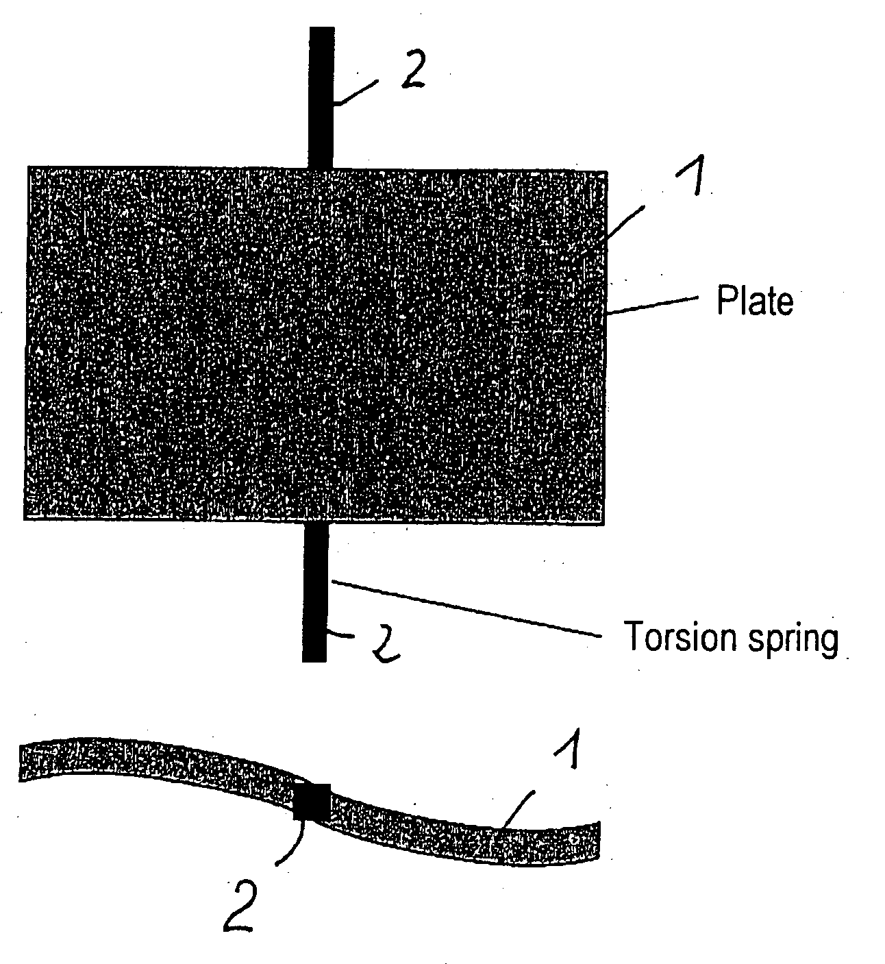
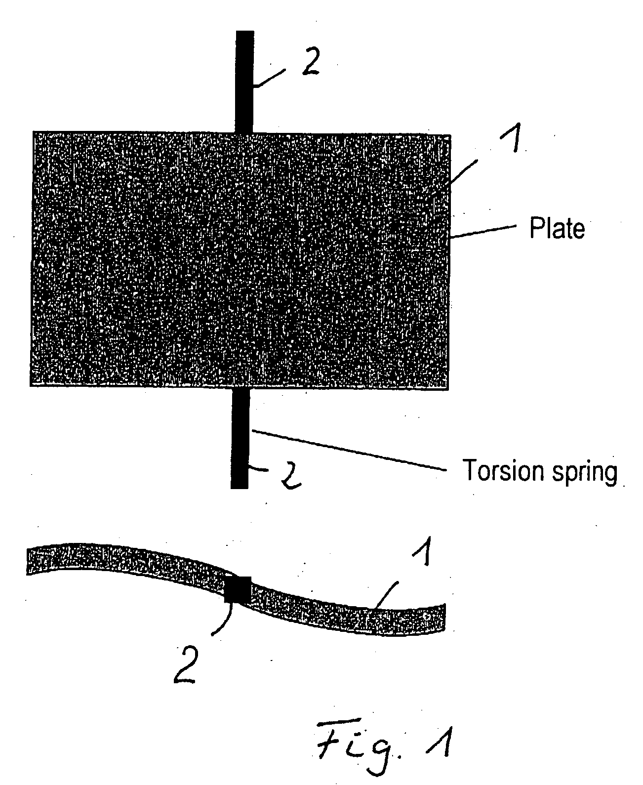
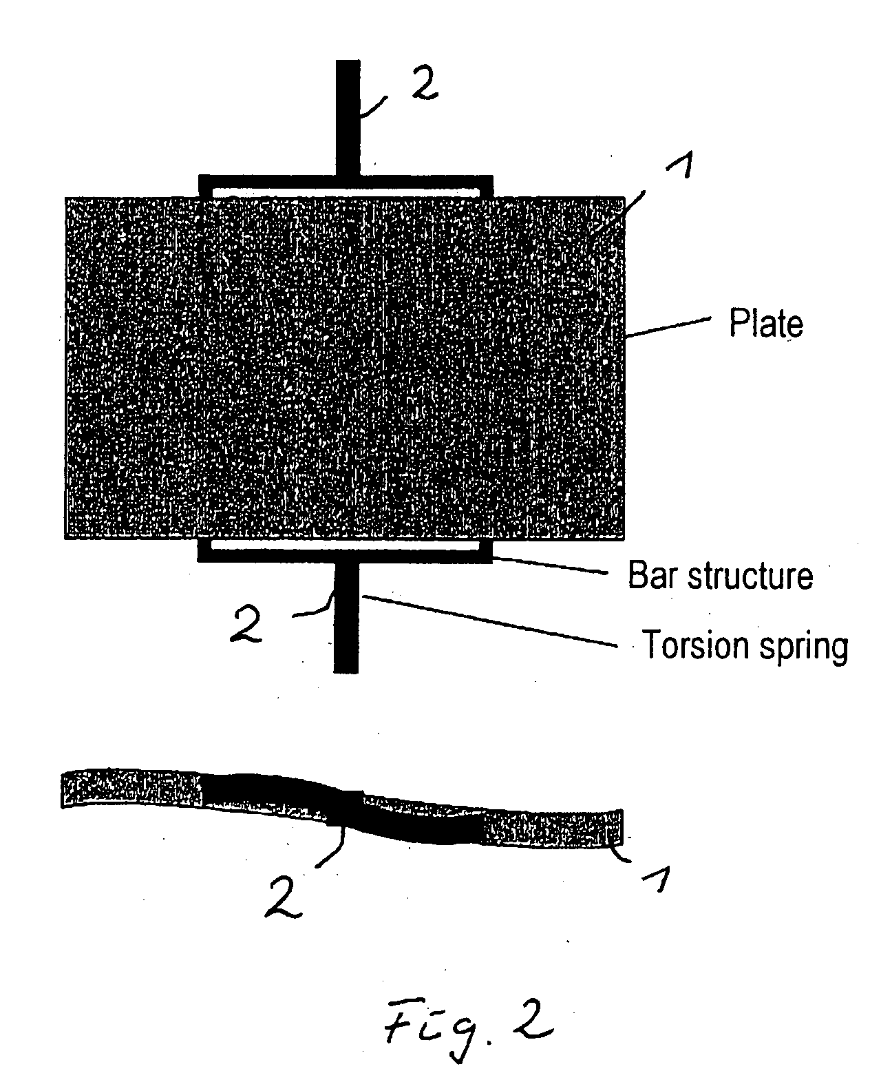
[0027] In the examples according to the prior art shown in FIGS. 1 and 2, in the same way as the example according to the invention which is shown in FIG. 3, the lower illustration shows the respective dynamic deformation of an element 1 which can be deflected by pivoting.

[0028] In the case of the example according to the invention shown in FIG. 3, five spring elements 2 are in each case provided on the two mutually opposite sides of an element 1 which can be deflected, in this case with a rectangular shape. A spring element 2 arranged centrally is arranged on the axis of rotation, about which the element 1 can be pivoted backwards and forwards within a predeterminable angle range. This is in the form of a pure torsion spring and in each case acts on the element 1 at only one point.

[0029] Each of the other four spring elements 2 then always acts on the element 1 at in each case two points at appropriate distances and with appropriate lever arms, while maintaining symmetrical relat...


PUM


Abstract

By way of example, in this example of the invention, it would also be possible to dispense in a manner which is not illustrated with the spring elements 2, and then for the element 1 to carry out an oscillating translational deflection. The invention relates to micromechanical optical elements having a reflective surface which can be deflected electrostatically or electromagnetically in a known manner and which can be used for a large number of applications. The object of the invention is to provide an element such as this at low cost and with improved dynamic deformation behaviour. The elements according to the invention with a reflective surface are in this case held by spring elements, in which case the element which can be deflected is held on mutually opposite sides by in each case at least two mutually independent spring elements.

Description

BACKGROUND [0001] The invention relates to micromechanical optical elements having a reflective surface, which can be deflected in a manner known per se by means of electrostatic or electromagnetic forces, such that incident electromagnetic radiation can be reflected as a function of the respective deflection of the element. The elements according to the invention can advantageously be used in deflection units for laser beams or light beams, bar-code readers, projection displays, retina scanning displays, readers for patterns and images, test equipment, laser printers or direct exposure devices. [0002] Micromirrors such as these are in this case deflected both translationally and rotationally and are then referred to as “pumping or tilting mirrors”. The deflection is in this case carried out at a very high frequency, so that corresponding accelerations occur. Since the deflected elements are normally in the form of plates with a different circumferential geometry, their moment of in...

Claims


Application Information

Patent Timeline
Patent Type & Authority Applications(United States)
IPC IPC(8): G06K7/10
CPCB81B3/007G02B26/085G02B26/0841B81B2201/042
Inventor WOLTER, ALEXANDERKLOSE, THOMAS
Owner FRAUNHOFER GESELLSCHAFT ZUR FOERDERUNG DER ANGEWANDTEN FORSCHUNG EV
Why Eureka
Try Eureka