
Rotatable utility belt mount

a technology of utility belts and mounts, which is applied in the field of utility belts, can solve the problems of not being able to allow, by design, the rotation of an article attached thereto, and the holster itself being uncomfortable to wear, so as to achieve the effect of reducing the amount of contortion and effor

Inactive Publication Date: 2007-02-01
BLADE TECH INDS
View PDF13 Cites 46 Cited by
  • Summary
  • Abstract
  • Description
  • Claims
  • Application Information

AI Technical Summary

Benefits of technology

[0017] Another object of the invention is to provide a rotatable mount which allows an object carried thereon the be removed with a minimum amount of contortion and effort.

Problems solved by technology

While the '169 belt clip is functional for its intended purpose, it does not allow, by design, for rotation of an article attached thereto.
While holsters provide protection for the handgun and the handgun user, the holsters themselves can be uncomfortable to wear, particularly by law enforcement personnel who must carry handguns while working.
For example, in many patrol cars, especially those with bucket seats, the holster is pushed upward by the seat and causes great discomfort.
Removing the handgun from its holster, however, reduces the protection afforded by the holster to a handgun, particularly where the holster secures the handgun within the holster to prevent unauthorized use of the handgun.
This may be difficult with used with modern law enforcement utility belts, which may have additional items secured to the utility belt.
U.S. Pat. No. 3,952,930 to Baldocchi, granted Apr. 27, 1976, depicts a rotational device for fastening an object to a belt, using conformal grooves on each half of the device, however, this device does not allow for rotation of the object relative to the belt once the device is adjusted.
This device does not allow for rotation of the object relative to the belt once the device is adjusted.

Method used


Image

  • Rotatable utility belt mount
  • Rotatable utility belt mount
  • Rotatable utility belt mount

Examples


Embodiment Construction

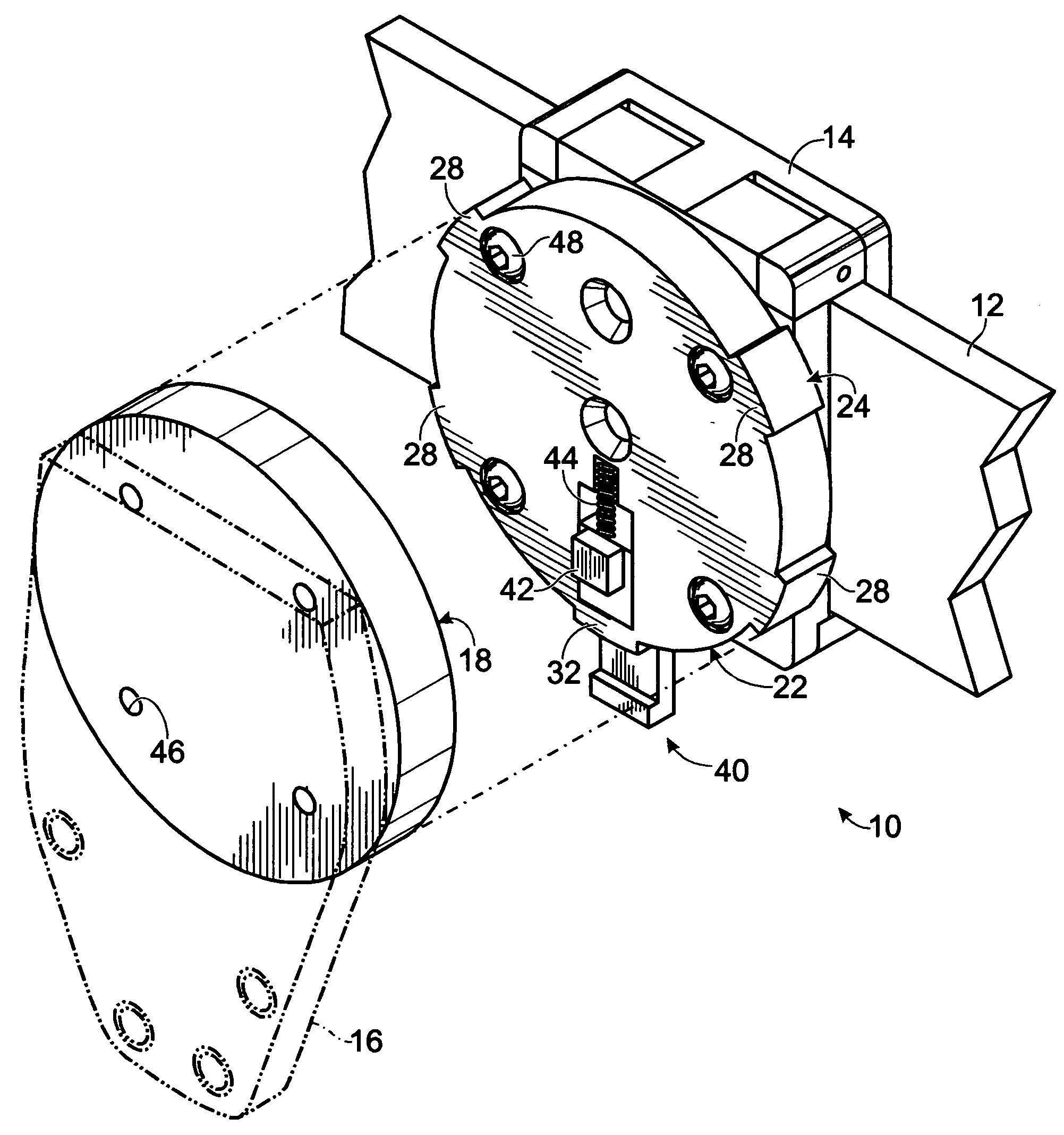
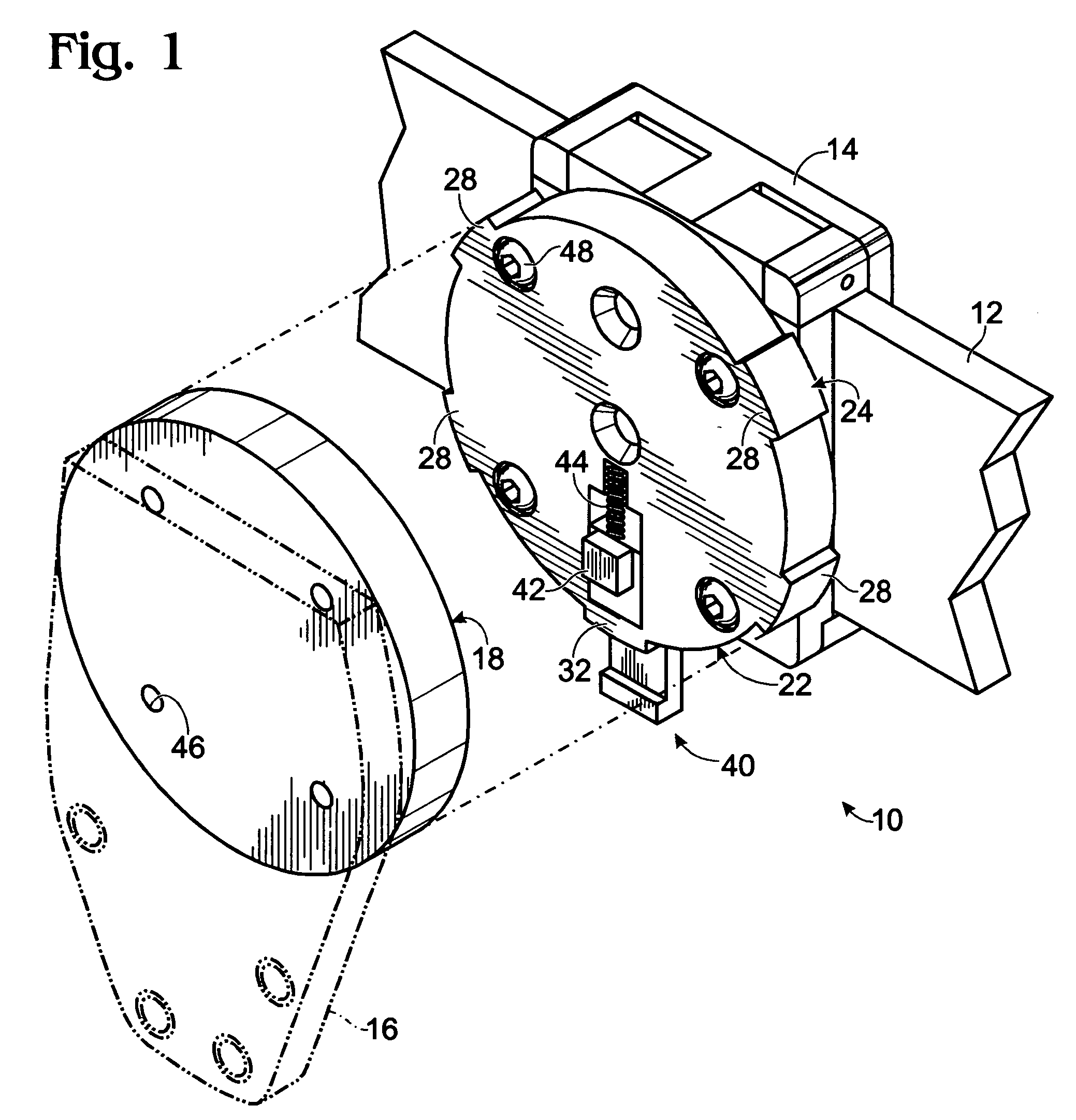
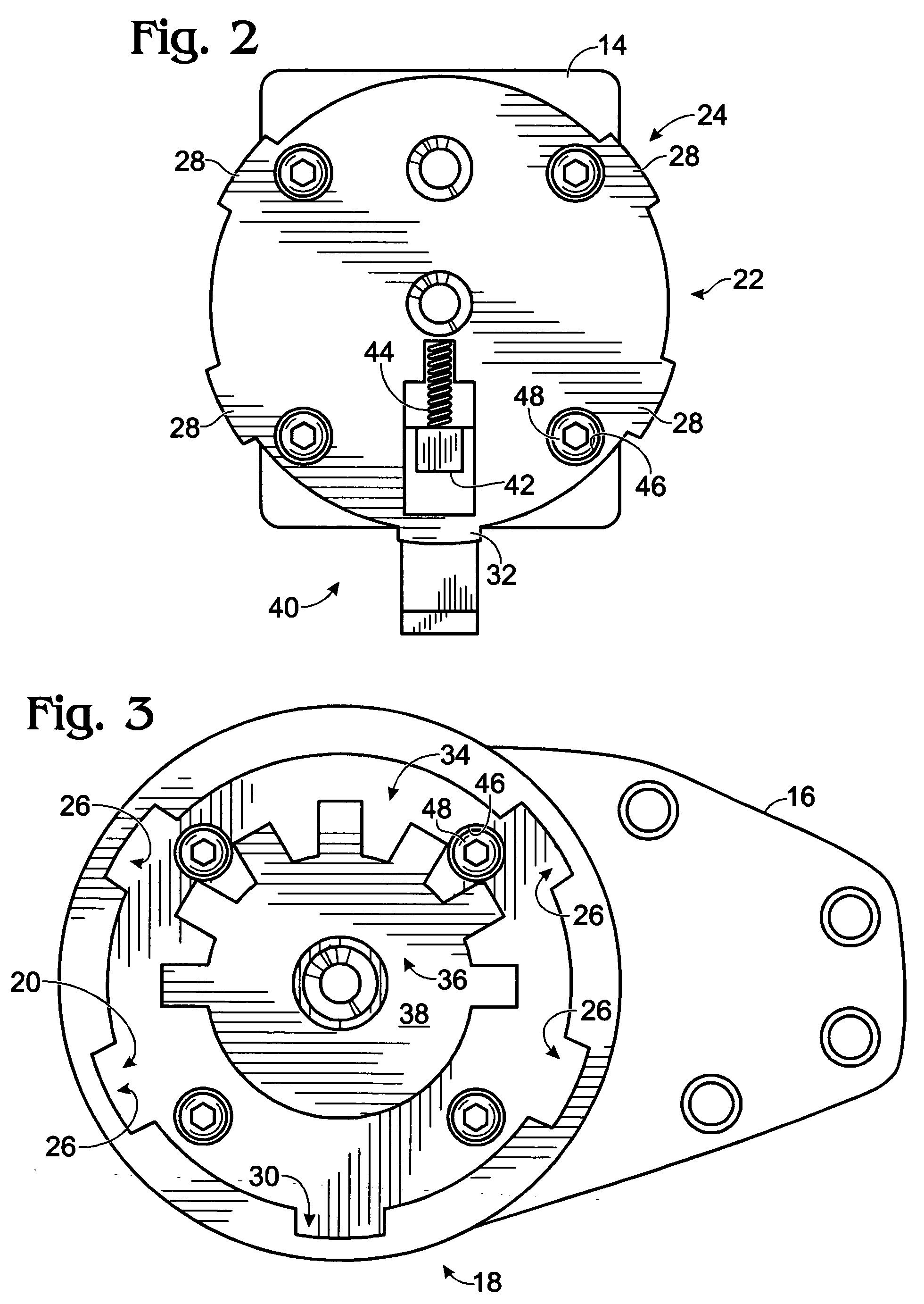
[0022] Referring now to FIGS. 1-3, the invention is rotatable utility belt mount, shown generally at 10 in FIG. 1, which is intended for use with a utility belt 12, a utility belt clip 14, and object 16 to be rotatably, removable secured to the utility belt. Rotatable utility belt mount 10 includes, and now referring to FIGS. 1-3, a first circular, planar disk element 18, having a first engagement structure 20 thereon for engaging a second circular, planar disk element 22, having a second engagement structure 24 thereon for engaging, in a rotatable, removal fashion, first engagement structure 20 of first circular, planar disk element 18.

[0023] First engagement structure 20 includes symmetrically arranged wasted regions 26 for receiving conformal symmetrically arranged lugs 28 of second engagement structure 24. First engagement structure 20 further includes a non-symmetrical wasted area 30 and second engagement structure 24 includes a non-symmetrical lug 32 wherein, with the symmetr...


PUM


Abstract

A rotatable utility belt mount for use with a utility belt and an object to be rotatably, removable secured to the utility belt includes a first circular, planar disk element, having an engagement structure thereon for engaging a second circular, planar disk, a second circular, planar disk element, having an engagement structure thereon for engaging, in a rotatable, removal fashion, the engagement structure of the first circular, planar disk element; an orientation mechanism for restricting rotational orientation of the second circular, planar disk element relative to the first circular, planar disk element; and a locking mechanism which restricts relative rotational movement and allows separation of the second circular, planar disk element from the first circular, planar disk element when the second circular, planar disk element is oriented to a specific orientation relative to the first circular, planar disk element.

Description

FIELD OF THE INVENTION [0001] This invention relates to utility belts, such as worn by law enforcement and military personnel, and specifically to a rotatable mount for securing and releasing a holder or holster to the utility in an adjustable fashion. BACKGROUND OF THE INVENTION [0002] A variety of devices are carried on utility belts by law enforcement officers and military personnel. Perhaps the most common item carried on a utility belt is a holster for a handgun, followed by a holster for a TASER™, a baton, pepper spray, radio, handcuffs, etc. Modern holsters offer a wide variety of features to protect a handgun within the holster and to secure the gun against unauthorized use. An example of such a holster is that manufactured by Blade-Tech Industries, Inc., which is molded to fit the contours of a specific make and model of firearm. Such holsters typically have a hard shell or skeleton made from a tough abrasion resistant polymer, such as glass-filled nylon, polypropalene, mod...

Claims


Application Information

Patent Timeline
Patent Type & Authority Applications(United States)
IPC IPC(8): A01K97/04F41C33/02
CPCF41C33/045
Inventor FORD, VINCENT GREGORY
Owner BLADE TECH INDS
Features
  • Generate Ideas
  • Intellectual Property
  • Life Sciences
  • Materials
  • Tech Scout
  • Unparalleled Data Quality
  • Higher Quality Content
  • 60% Fewer Hallucinations
Learn More